Electrical connector for insulated conductive wires encapsulated in protective tubing

a technology of protective tubing and electrical connector, which is applied in the direction of cable installation in underground tubes, coupling device connections, and well accessories, etc., can solve the problems of cable protective housing, difficult to maintain a durable electrical connector, and substantial difficulty in providing a sealed electrical connection. , to achieve the effect of extending the longitudinal dimension

a technology of protective tubing and electrical connector, which is applied in the direction of cable installation in underground tubes, coupling device connections, and well accessories, etc., can solve the problems of cable protective housing, difficult to maintain a durable electrical connector, and substantial difficulty in providing a sealed electrical connection. , to achieve the effect of extending the longitudinal dimension

US20080026623A1Active Publication Date: 2008-01-31QUICK CONNECTORS

Image

  • Electrical connector for insulated conductive wires encapsulated in protective tubing
  • Electrical connector for insulated conductive wires encapsulated in protective tubing
  • Electrical connector for insulated conductive wires encapsulated in protective tubing

Examples


Embodiment Construction

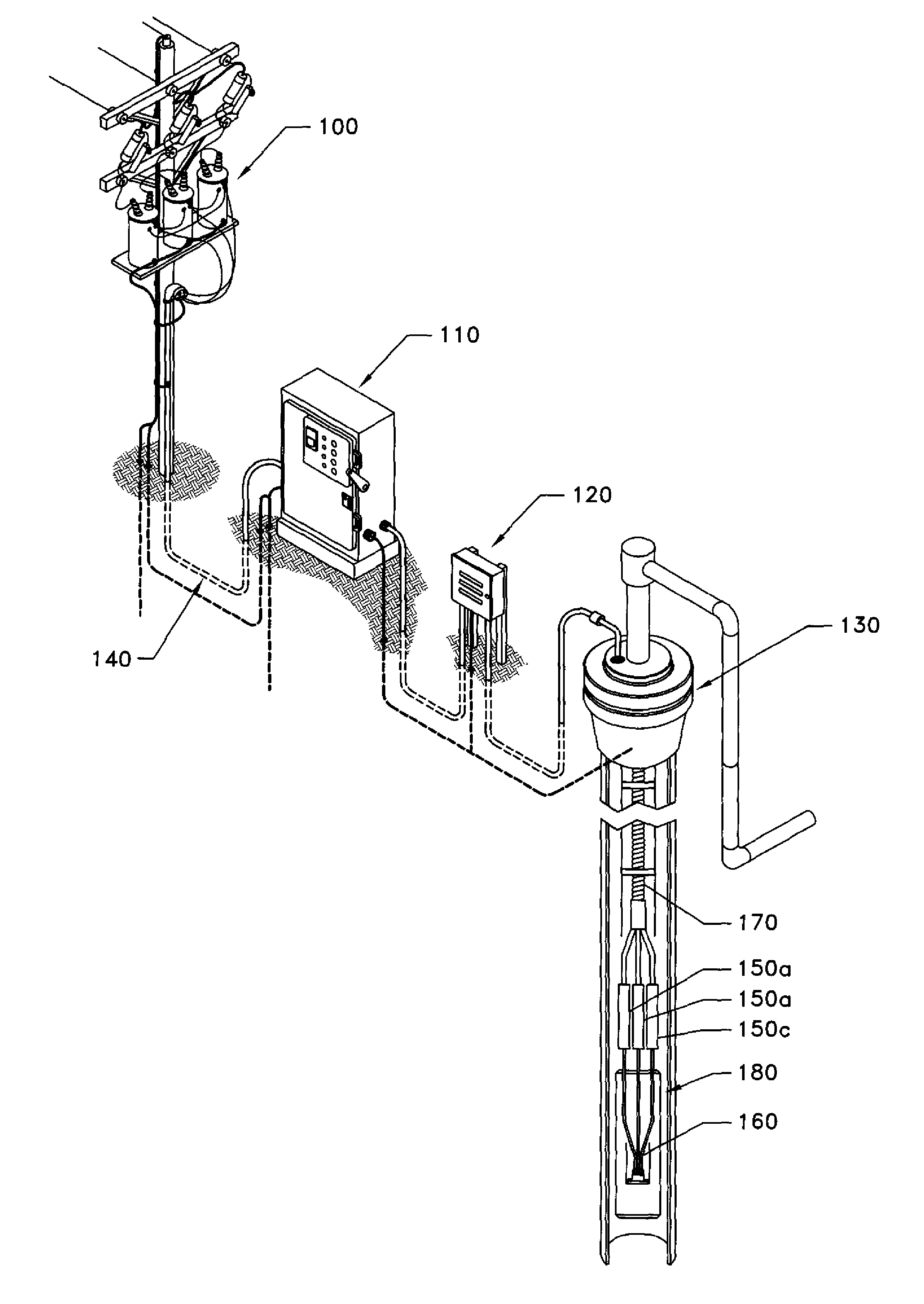
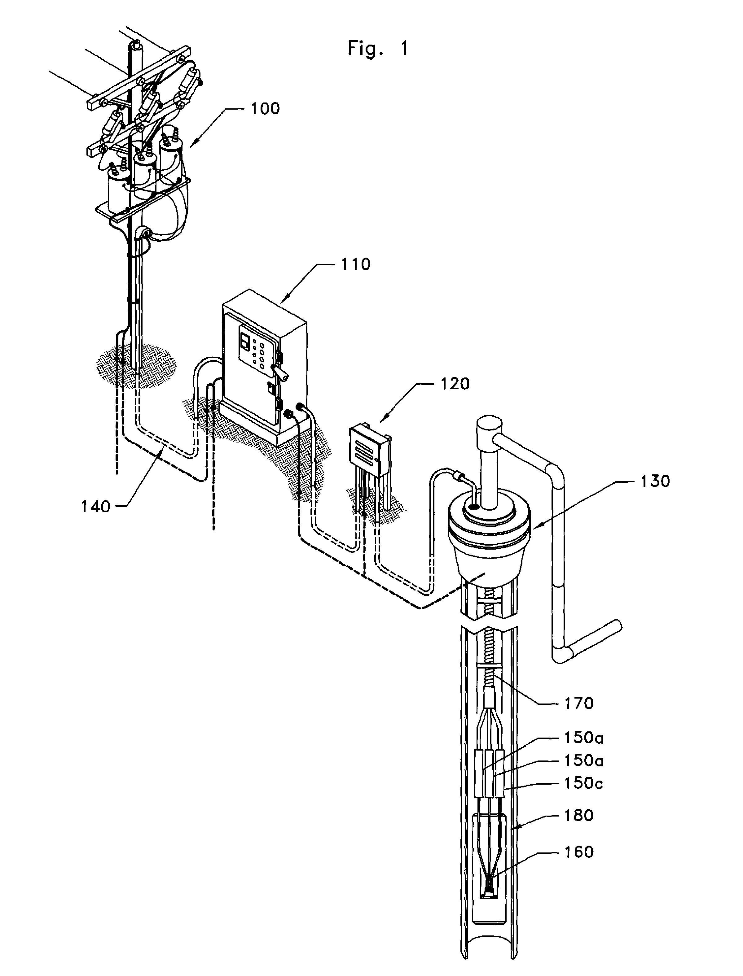
[0036]FIG. 1 illustrates a preferred embodiment in which a remote surface power source 100 provides electrical power to down hole electrical equipment 180. The remote power source 100 is preferably a transformer bank, positioned on a power pole, which supplies power via cable 140 to motor control panel 110. Power cable 140 is typically formed of a medium voltage electrical conductor cable that runs from the motor control panel 110 in a known way to a vented junction box 120, and then into a wellhead barrier 130 of an underground well. Inside the well, a main power cable 170 extends from below the wellhead barrier 130 to a position proximate the down hole electrical equipment 180, where it connects with a motor lead extension cable 160. As further described below, preferred and alternative embodiments of the present invention, connectors 150a, 150b, and 150c (referred to generally as connector 150) provide the means for connecting the main power cable 160 and the motor lead extension...


PUM


Abstract

A connector for electrically and mechanically connecting insulated conductor wires encapsulated in protective tubing. Embodiments of the connector provide a protective outer sheathing that circumscribes the conductive and insulating structures within the connector. The connector is formed with a plurality of tubular fitting assemblies for securely attaching the connector to down hole electrical power cables. The connector is also formed with an internal insulating boot having an internal passage adapted to surround the conductive elements of the connector to provide a reliable down hole electrical connector.

Description

CROSS-REFERENCE TO RELATED APPLICATIONS [0001] This application claims the benefit of U.S. Provisional Application Ser. No. 60 / 833,880 filed Jul. 28, 2006, the contents of which is hereby incorporated by reference in its entirety.TECHNICAL FIELD [0002] The present invention relates to an electrical power cable connector sealing method and assembly for an underground well and, more particularly, to a unique, efficient sealed electrical connector assembly for coupling the conductive wires of a motor lead extension cable with the conductive wires of other power cables. BACKGROUND OF THE INVENTION [0003] Substantial difficulty has heretofore been encountered in providing a sealed electrical connection between a motor lead extension cable and other types of power cables. Particular difficulty has also arisen in maintaining a durable electrical connector that is resistant to the harsh down hole environments often responsible for causing electrical failures between surface power sources an...

Claims


Application Information

Patent Timeline
31 Jan 2008
Publication
US20080026623A1
IPC
H01R13/523
CPC
E21B43/128; H01R13/59; H01R13/523; H01R4/70; H01R13/5205; H02G9/06
Inventors
EMERSON, TOD D.