
Hand cleaning tool with removeable cleaning head

a cleaning head and cleaning tool technology, applied in the field of hand cleaning tools, can solve the problems of insufficient cleaning elements in the attachment device currently in use, the difficulty of replacing the cleaning element on many tools, so as to eliminate the risk of injury to the user, facilitate and simplify the use, and allow cleaning versatility

Inactive Publication Date: 2008-02-07
NICELIFE
View PDF16 Cites 24 Cited by
  • Summary
  • Abstract
  • Description
  • Claims
  • Application Information

AI Technical Summary

Benefits of technology

[0003]It is an object of the present invention to provide a hand cleaning tool of a configuration which solves many of the problems associated with the use of tools for cleaning soiled surfaces.
[0004]It is another object of the present invention to provide a hand cleaning tool which is safe for manual use and will eliminate risk of injury to the user during cleaning operations.
[0005]It is a further object of the present invention to provide a hand cleaning tool which is easy and simple to use and is ergonomically designed for efficient use.
[0006]It is another object of the present invention to provide a hand cleaning tool which is configured for use with cleaning elements of varying surfaces to allow cleaning versatility.
[0007]It is still another object of the present invention to provide a hand cleaning tool which prevents its cleaning element from separating or falling off the tool, especially during vigorous usage.
[0008]It is a further object of the present invention to provide a hand cleaning tool which employs cleaning elements which are easily replaceable when elements need to be cleaned or replaced with new elements.

Problems solved by technology

However, prior cleaning tools which employ the use of removable cleaning elements each have disadvantages.
The attachment devices currently in use generally do not adequately retain the cleaning elements on the cleaning tools during vigorous cleaning operations.
Replacement of cleaning elements is also difficult on many tools.
Often the design of the tool and the position of its cleaning element restrict its versatility.
Others are not ergonomically designed to allow the user to clean efficiently with the tool.
In addition, the configuration of many tools does not adequately protect the hand of the user during the cleaning operation.

Method used


Image

  • Hand cleaning tool with removeable cleaning head
  • Hand cleaning tool with removeable cleaning head
  • Hand cleaning tool with removeable cleaning head

Examples


Embodiment Construction

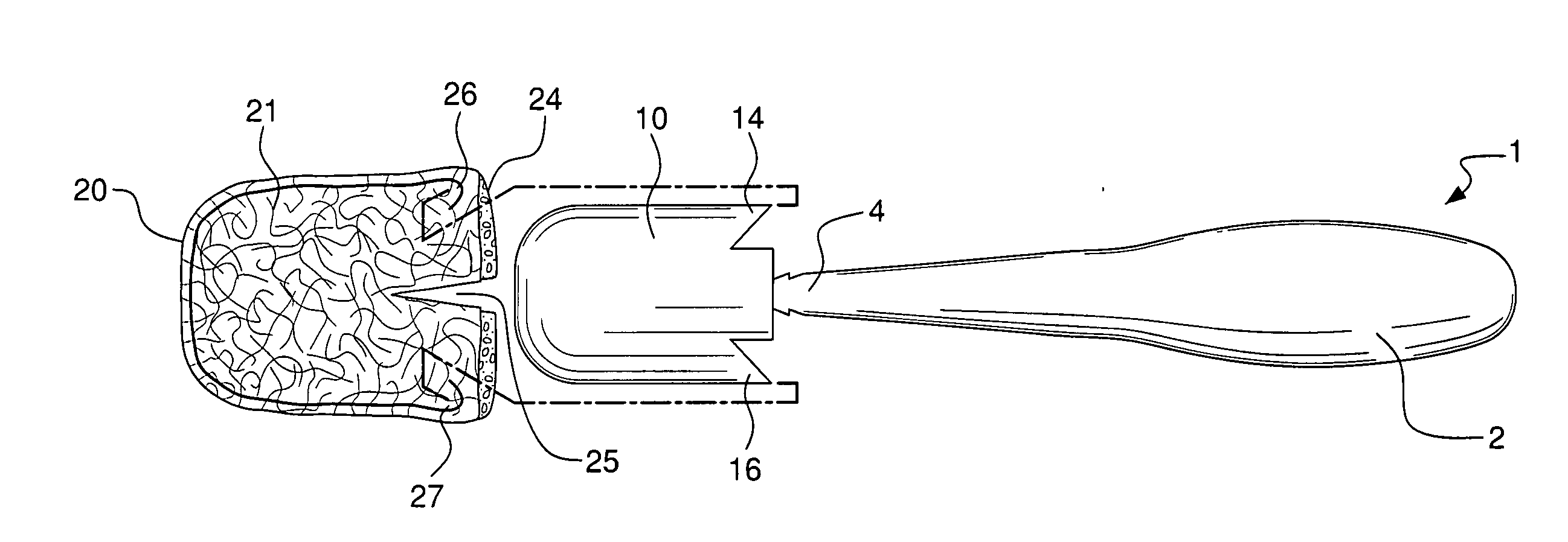
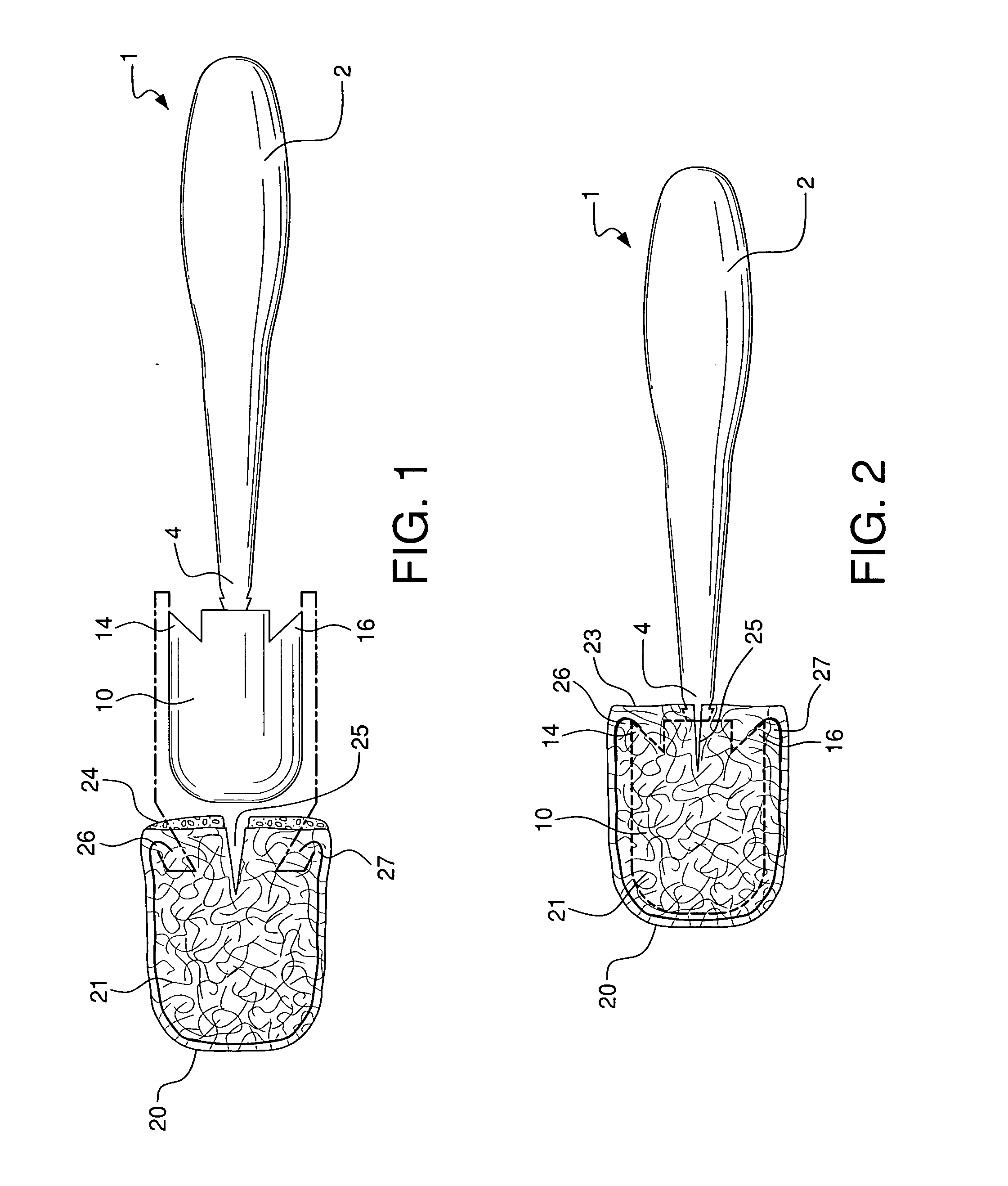
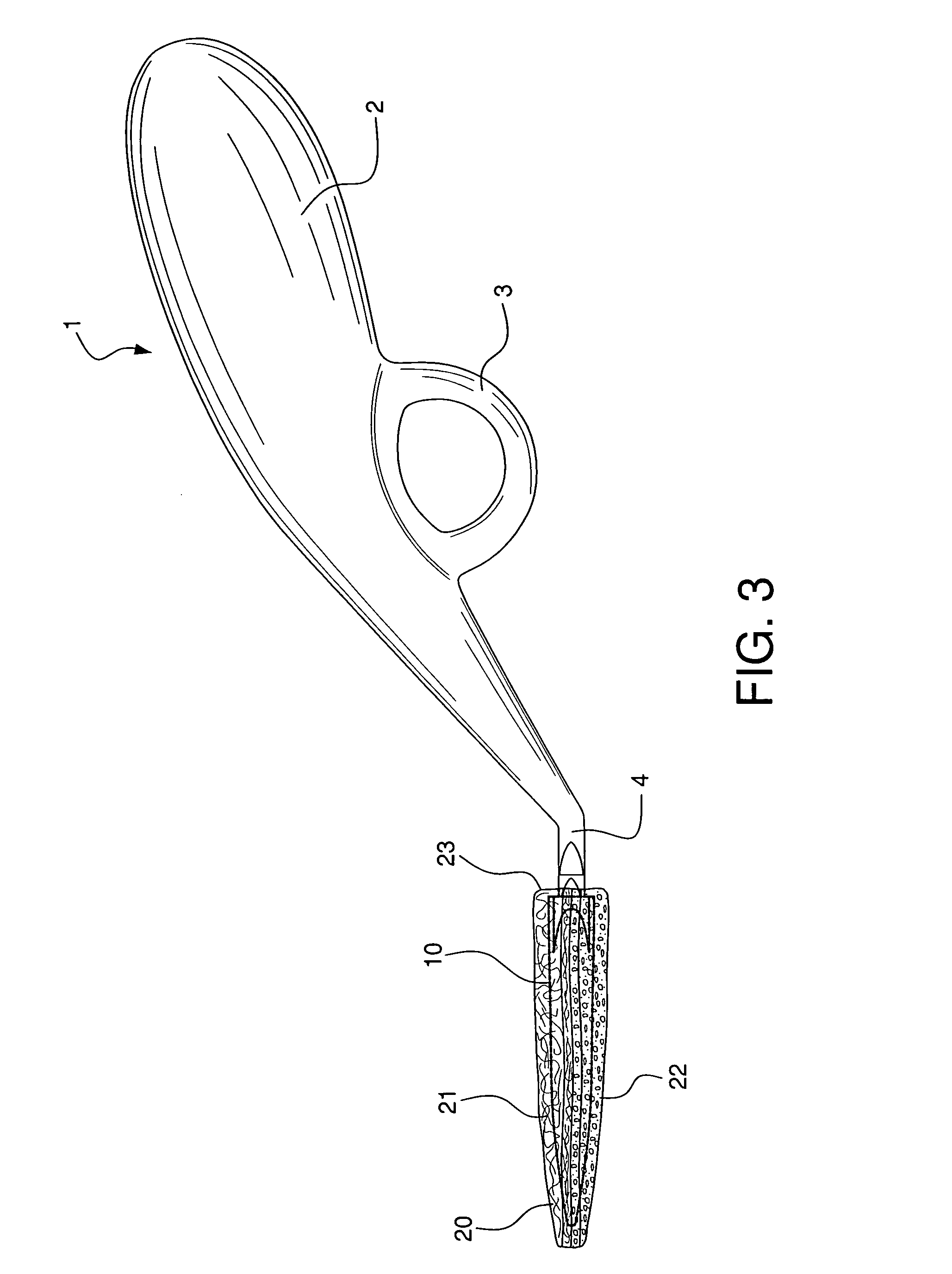
[0014]Hand cleaning tool 1 comprises a unitary cleaning tool body having handle 2 and cleaning head 10. Handle 2 comprises a hand-gripping section and optional finger support 3 extending from the gripping section. Cleaning head 10 consists of a flexibly rigid support member which extends outwardly at an obtuse angle from end 4 of handle 2. Cleaning head 10 also comprises outwardly extending locking tabs 14 and 16, substantially “V” shaped in configuration, located on opposite sides of the cleaning head.

[0015]Cleaning pad 20 is mitt-like in configuration, with rearward linear edge 23. Opening 24 extends the length of edge 23 and allows access into pad 20. Formed within the interior of pad 20 and on either side of it are pockets 24 and 26. It is contemplated that these pockets will be formed by sewn joints, but equivalent joint connections, e.g. tacking, glue etc. can be used. Slit 25 extends inwardly from rearward edge 23. Separating and opening slit 25 serves to expand pad 20 and it...


PUM

PropertyMeasurementUnit
perimeteraaaaaaaaaa
shapeaaaaaaaaaa
abrasiveaaaaaaaaaa

Abstract

A handheld cleaning tool has a tool body with an ergonomically designed handle and cleaning head, the cleaning head extending at an obtuse angle to the handle. The cleaning head has a flexibly rigid support member with outwardly extending locking tabs located at each side of the member. The cleaning head is configured to be inserted into a mitt-like cleaning pad which substantially encompasses the cleaning head when it is fully inserted into the pad. When the cleaning head is fully within the pad, the locking tabs are immovably positioned within pockets on opposite sides of the pad. This secures the pad on the cleaning head and to the handle of the cleaning tool. The outer surfaces of the cleaning pad can accommodate an abrasive surface, a sponge-like surface, or other equivalent, commonly used cleaning surfaces. Removal and replacement of the cleaning pad from the cleaning head is accomplished by separating and opening a slit within the cleaning pad, which permits removal of the cleaning head and allows replacement with a clean pad.

Description

BACKGROUND OF THE INVENTION[0001]There are a variety of different hand cleaning tools designed to efficiently enable a user to manually clean soiled surfaces on dishes, pots, pans, utensils, and similar soiled articles. Those tools which have removeable cleaning pads, brushes, scouring material, or like cleaning elements use different means to secure the element to the tool. For instance, cleaning elements are commonly attached by serrated projections, burrs, tacks, and similar sharp extensions which dig into the cleaning material to hold it. A variety of clamps, grippers, retaining ribs and various configurations of holding devices are also used to secure cleaning elements to their tools. However, prior cleaning tools which employ the use of removable cleaning elements each have disadvantages. The attachment devices currently in use generally do not adequately retain the cleaning elements on the cleaning tools during vigorous cleaning operations. Replacement of cleaning elements is...

Claims


Application Information

Patent Timeline
Patent Type & Authority Applications(United States)
IPC IPC(8): A47L13/10
CPCA47L17/08A47L13/46
Inventor PETNER, ROBERT E.GENGLER, CHARLES E.
Owner NICELIFE
Learn More