
Apparatus and Method for Replicating a Plantar Surface of a Foot

a technology of plantar surface and replicating device, which is applied in the field of replicating device and method for personally fitting biomechanical orthopedic insole, can solve the problems of large difference of specific load for various uneven distribution of load on the sole's load-bearing surface, and large difference of specific load for different areas of the sole, so as to improve the reliability of sensing and reduce production costs.

Inactive Publication Date: 2008-02-07
NUDELMAN WILLYN +1
View PDF12 Cites 22 Cited by
  • Summary
  • Abstract
  • Description
  • Claims
  • Application Information

AI Technical Summary

Benefits of technology

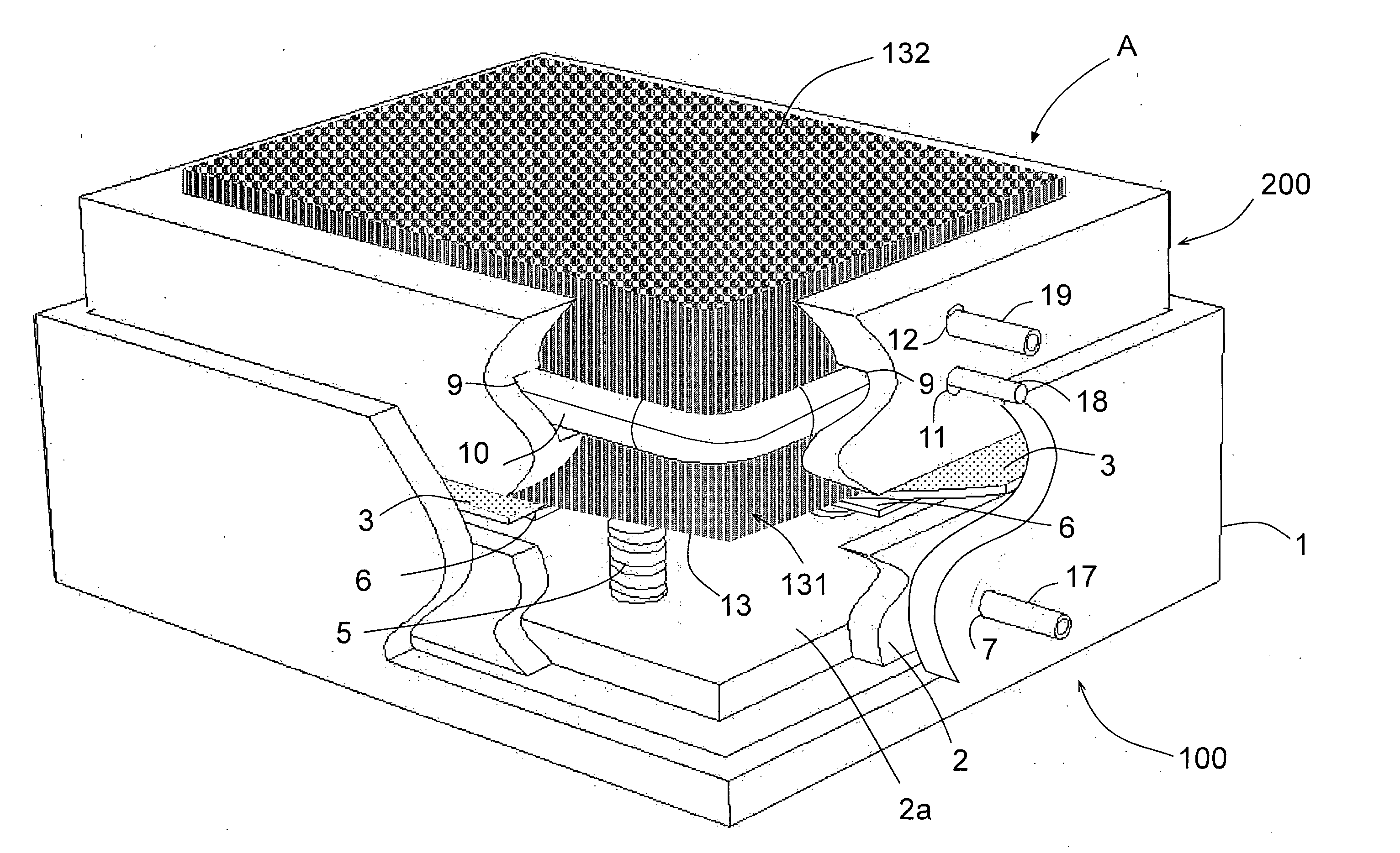
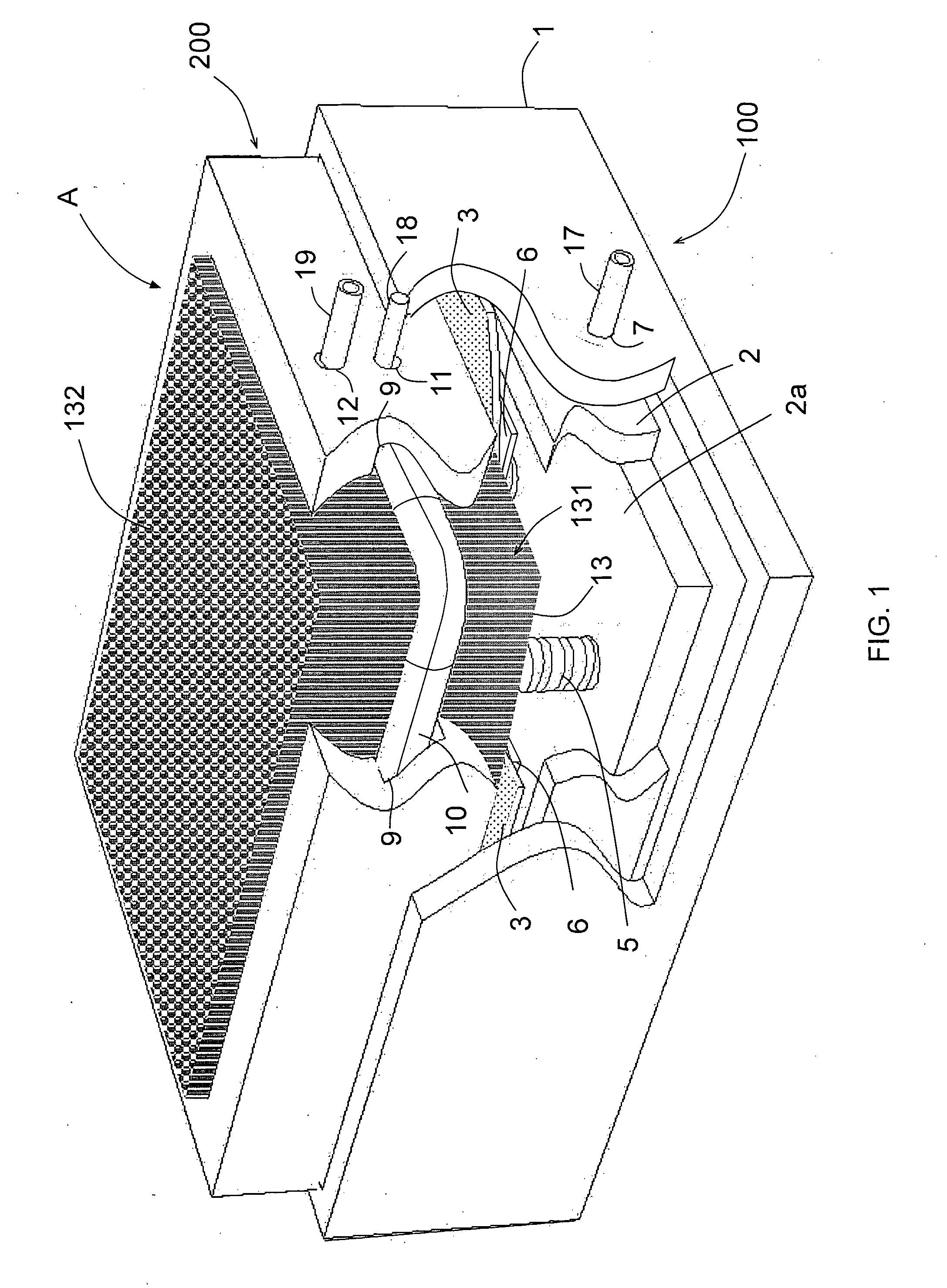
[0012] The rods may be circular in cross-section, or may have cross-section that more closely tessellates, such as square or hexagonal. The use of a tessellating cross-section minimizes the gaps between the rods, with the beneficial effect that any molding compound used to form a replicate is less likely to seep into the bed of rods.
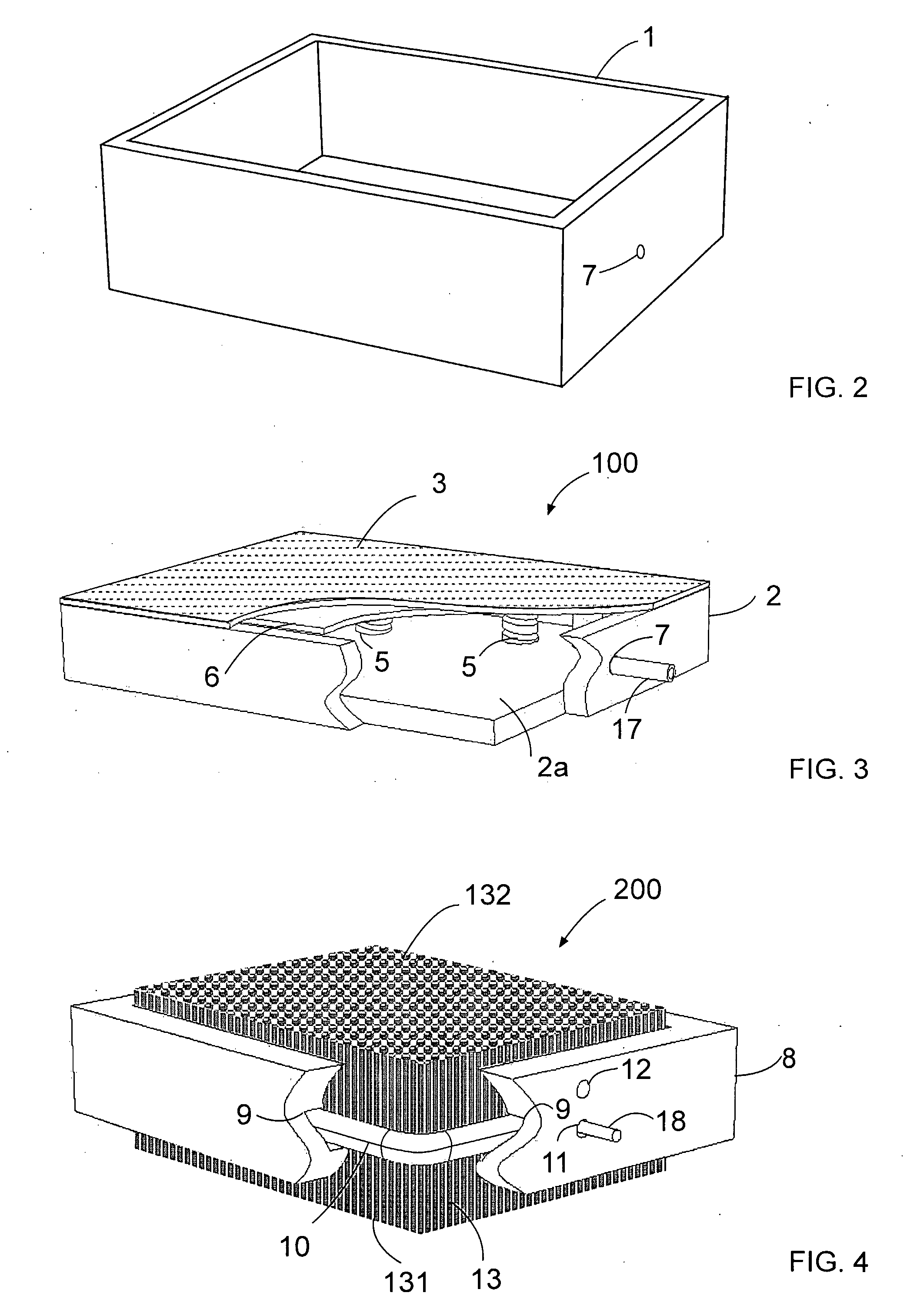
[0015] According to an embodiment of the invention, the apparatus further comprises a moveably mounted platform within the cavity, substantially parallel to, and biased towards the membrane. This platform serves, initially to support the object (e.g. a foot), prior to introduction of the fluid. As fluid is introduced into the chamber, the biasing of the platform (e.g. with one or more springs) causes the platform to move with the foot, until the foot is completely supported by the fluid-backed membrane. Preferably, in this embodiment, the device further comprises sensing elements, to sense contact between the elastic membrane and the platform resulting from deformation of the membrane, in use. The sensor element, in this case, may be conveniently located between the platform and the opposite face of the container, and could take the form of a microswitch. Several such sensor elements may be employed—for example, on each corner of the platform—to improve the reliability of the sensing. This serves a similar function to the sensing elements described above.
[0016] According to one embodiment of the apparatus, the clamping unit comprises a reversibly deformable tube encircling at least part of the bed of rods, the reversible clamping being achieved by manipulation of the pressure of fluid within the tube, the resultant deformation of which tube squeezes the rods together. Use of an apparatus such as this is particularly advantageous, as the same fluid introduction means as used in the chamber can also be used to drive the clamping unit. In this way, production costs can be minimized.
[0017] Alternatively, the clamping unit can comprise an electromagnet acting upon a bed of magnetically susceptible rods. In this way, clamping and unclamping can be carried out rapidly, and without the use of fluid systems, which can leak.
[0018] In a particularly advantageous embodiment, the device further comprises a deformable airtight enclosure surrounding the bed of rods, and means to reversibly remove air from within the enclosure. This enclosure—such as a bag—serves two functions: firstly, when it is “vacuum sealed” around the bed of rods, is serves as an additional or alternative clamping mechanism, enabling the clamped bed of rods to be removed from the apparatus for use as a mould. In this way, a number of rod beds may be used with the same apparatus, enabling the apparatus to be used whilst molding is taking place, without needing to replicate the clamping mechanism. Secondly, the enclosure also acts to seal any gaps between the rods down which molding compound might migrate, sticking the rods together and resulting in an uneven surface on the molded item.
[0028] It should be noted that the invention allows production of insoles using a loaded foot imprint, taking into consideration the patient's weight and the area of the load-bearing surface of the foot. This ensures equal distribution of the specific load across the surface of the sole during walking and standing.

Problems solved by technology

In the first case, the shape of the foot imprint does not represent its contour under load conditions, and therefore, the distribution of the load on the sole's load-bearing surface appears uneven, because of the differences of the elastic characteristics of the soft tissue and the differences of mobility of the bone elements.
Such unevenness creates large difference of specific load for various areas of the sole.
The hard surface loading generates large difference of specific load for different areas of the sole, due to the unequal mobility of the bone elements.
The consequences of such uneven distribution of pressure in different foot areas are callosities, pain and considerable strains that could result in fracture.
Selecting elastic materials with fine adjustment of parameters to suit every individual case is impractical, which limits the usage of this method.

Method used


Image

  • Apparatus and Method for Replicating a Plantar Surface of a Foot
  • Apparatus and Method for Replicating a Plantar Surface of a Foot
  • Apparatus and Method for Replicating a Plantar Surface of a Foot

Examples


Embodiment Construction

[0045] The principles and operation of an apparatus for replicating the profile of a surface of a sole according to the present invention may be better understood with reference to the accompanying description and the drawings, in which preferred embodiments of the invention are illustrated. It should be understood that these drawings are given for illustrative purposes only and are not meant to be limiting. The present invention may be embodied in many different forms and should not be construed as limited to the embodiments set forth herein. The same reference numerals and alphabetic characters will be utilized for identifying those components which are common in the surgical fastener and its components shown in the drawings throughout the present description of the invention.

[0046] Referring to FIG. 1 through FIG. 5 together, an apparatus A for replicating the profile of a plantar surface of a foot (i.e., surface of the sole) includes an inflation device 100 (shown separately in...


PUM

PropertyMeasurementUnit
pressure resistantaaaaaaaaaa
pressureaaaaaaaaaa
lengthaaaaaaaaaa

Abstract

An apparatus and method for replicating the profile of a plantar surface of a foot are provided. It has particular application in the production of footwear insoles, the apparatus comprises a pressure resistant container (2); an elastic membrane (3) sealed to an open face of the container, thereby defining a variable volume chamber within the container; means for reversibly introducing fluid (15) into the chamber; a bed of elongate rods (13) of substantially equal length, in which, in one configuration, the rods can slide freely, one relative to another, along their length; and clamping means (10) for reversibly clamping the bed of rods so that the relative sliding movement of the rods is resisted; the bed of rods being arranged, in use, outside the container so that ends of the rods abut the face of the membrane. In this way, a positive and negative mould of the surface can be formed.

Description

FIELD OF THE INVENTION [0001] The present invention relates to the field of devices and methods for replicating uneven surfaces, and more particularly, to an apparatus and method for production of personally fitted biomechanical orthopedic insoles. BACKGROUND OF THE INVENTION [0002] It is recognized that due to structural deficiencies or deformities of the feet many individuals may suffer from various states of foot pain, and / or physical discomfort ranging from minor back pains to severe disability. Orthopedic insoles can compensate for the structural deficiencies of an individual's foot or position. For individuals suffering from pain in these areas, orthopedic insoles can provide a measure of relief. For others, such as professional athletes and soldiers orthopedic insoles can reduce the chance of injury while improving freedom of motion. [0003] Conventional methods and devices for making orthopedic insoles are based on production of a gypsum foot imprint on which the orthopedic i...

Claims


Application Information

Patent Timeline
Patent Type & Authority Applications(United States)
IPC IPC(8): A43D1/00A61B5/00A61B5/103
CPCA43D1/022A61B5/1036B29C33/302A61B5/1077A61B5/1074
Inventor NUDELMAN, WILLYNNUDELMAN-KLEPFISH, MARINA
Owner NUDELMAN WILLYN
Learn More