
Hydrate-based desalination using compound permeable restraint panels and vaporization-based cooling

a technology of permeable restraints and desalination hydrates, applied in the direction of support, cooling apparatus, lighting and heating apparatus, etc., can solve the problems of not being able to purify such slurries sufficiently, blocking permeability, and filling pores, so as to maintain the saturation level of hfm

Inactive Publication Date: 2008-02-07
MARINE DESALINATION SYST L L C
View PDF24 Cites 0 Cited by
  • Summary
  • Abstract
  • Description
  • Claims
  • Application Information

AI Technical Summary

Benefits of technology

"The present invention is a method for desalinating or purifying water using a hydrate-forming material (HFM). The method involves introducing water to be treated into an enclosure containing one or more HART modules, which include one or more HART restraint panels with pores extending from one major surface of the panel to an opposite major surface. HFM is then introduced into the water to be treated within the enclosure. The water to be treated is cooled to a temperature at which hydrate of the HFM forms at pressure conditions within the enclosure, causing the hydrate to form within the pores of the HART restraint panels, sealing them. The HFM can be recovered and reused in further cycles of desalination or purification. The method can be used at depth within a body of water by creating pressure conditions within the enclosure. The recovered HFM can be mixed with the water to be treated to maintain saturation levels. The method improves on previous methods by using a more efficient cooling process and allowing for more hydrate formation within the pores of the HART restraint panels."

Problems solved by technology

Thus far, it has not been possible to purify such slurries sufficiently for the direct injection of HFM into seawater to be a viable process for commercially producing fresh water because too much low-salinity water had to be consumed washing the slurry.
Lowering temperature of the chilled surface causes hydrate to form on it and in its vicinity, thus filling the pores and blocking permeability.

Method used


Image

  • Hydrate-based desalination using compound permeable restraint panels and vaporization-based cooling
  • Hydrate-based desalination using compound permeable restraint panels and vaporization-based cooling
  • Hydrate-based desalination using compound permeable restraint panels and vaporization-based cooling

Examples


Embodiment Construction

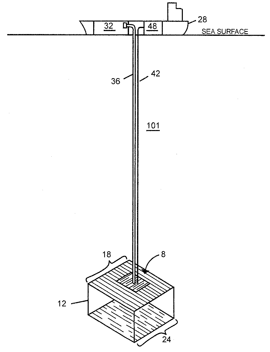
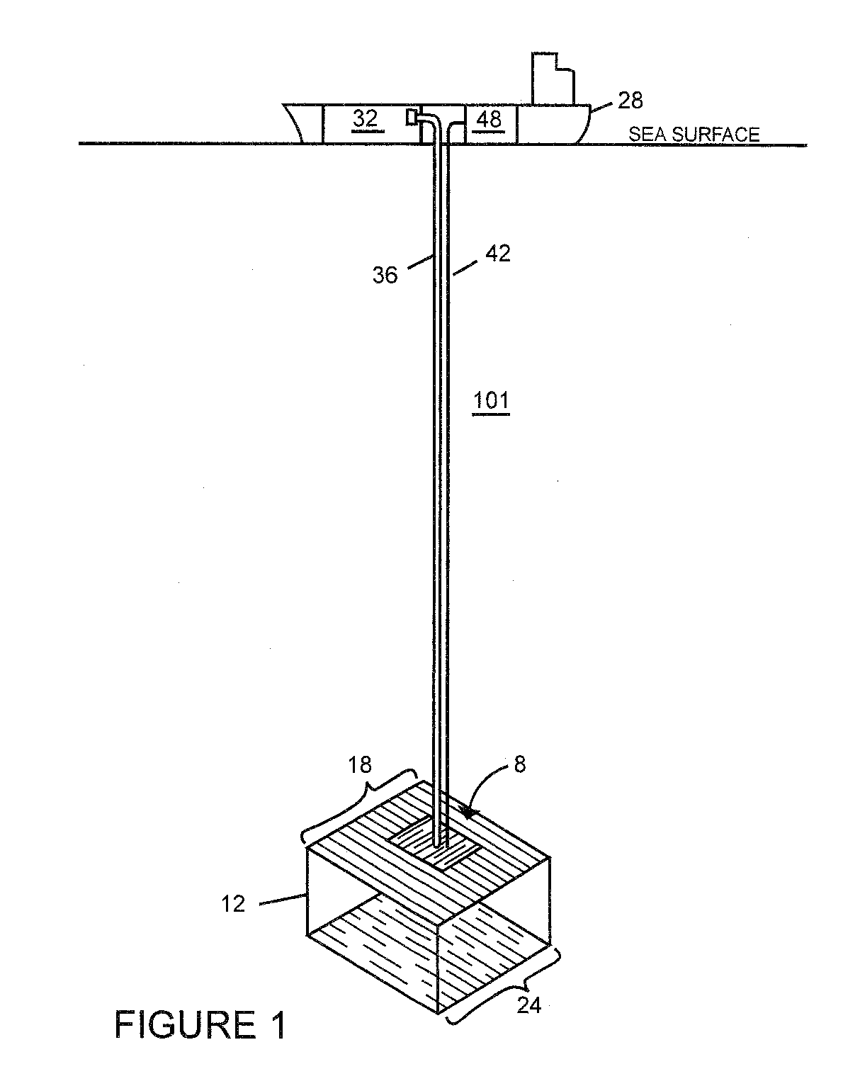
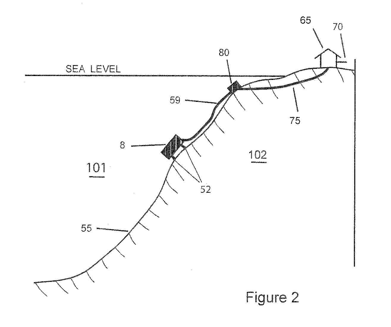
[0059]In general, according to the invention, gas hydrate (clathrate) is formed on permeable restraints broadly utilizing the approach of my patents that are referenced above, which restraints are housed within an enclosure. The enclosure may be submerged within a naturally occurring body of water (FIGS. 1 and 2), or it may be an artificially pressurized vessel (FIG. 31). Hydrate-forming material (HFM) is infused into the water being treated, and the permeable restraints are chilled by means of an internal cooling system (illustrated and described in much greater detail below) so that hydrate forms on the surfaces of the permeable restraints. Furthermore, utilizing the approach to desalination taught in my above-referenced patents, the hydrate is caused to dissociate through the permeable restraints, thereby releasing HFM and relatively purified water. The HFM may be captured for further infusion into water being treated, and the purified water is gathered for consumption (possibly ...


PUM


Abstract

Desalination apparatus based on porous restraint panels fabricated from a number of different layers of metal, thermoplastic, or other substances are used as sophisticated heat exchangers to control the growth of gas hydrate. The gas hydrate is produced after infusion of liquid hydrate-forming material into water to be treated, which liquid hydrate-forming material can also be used to carry out all the refrigeration necessary to cool seawater to near the point of hydrate formation and to cool the porous restraint panels. Hydrate forms on and dissociates through the porous restraints. The composite restraint panels can also be used in gaseous atmospheres where, for instance, it is desired to remove dissolved water.

Description

CROSS REFERENCE TO RELATED APPLICATIONS[0001]This application is a continuation of application Ser. No. 11 / 785,033 filed Apr. 13, 2007, the contents of which are incorporated by reference. That application is based on and claims the priority benefit of U.S. provisional application 60 / 811,760 filed Jun. 8, 2006, the contents of which are also incorporated herein by reference.GOVERNMENTAL SUPPORT AND INTEREST[0002]This invention was made with Governmental support under ONR CONTRACT: N00014-04-C-0237 dated Jun. 4, 2004, and amended May 18, 2005, and issued by the Office of Naval Research. The Government has certain rights in the invention.FIELD OF THE INVENTION[0003]In general, the invention relates to desalination and water treatment / purification. More particularly, the invention relates to apparatus and methodologies for permeable restraint-supported hydrate formation and dissociation used to achieve such desalination and water treatment.BACKGROUND OF THE INVENTION[0004]Gas hydrate f...

Claims


Application Information

Patent Timeline
Patent Type & Authority Applications(United States)
IPC IPC(8): F25B27/00F25D25/00
CPCC02F1/22C02F1/26F28F3/12F28D21/0015F28F3/086C02F2103/08Y02A20/124
Inventor MAX, MICHAEL DAVID
Owner MARINE DESALINATION SYST L L C
Learn More