[0039] According to the present invention, when the movable member is moved so that the printer head retreats from the
backup roller, the gap between the printer head and the backup roller widens and the tension bar separates from the ink tape. This permits the ink tape to be more easily inserted between the printer head and the backup roller and thus permits the ink ribbon to be more easily detached and attached. PREFERRED EMBODIMENTS OF THE INVENTION
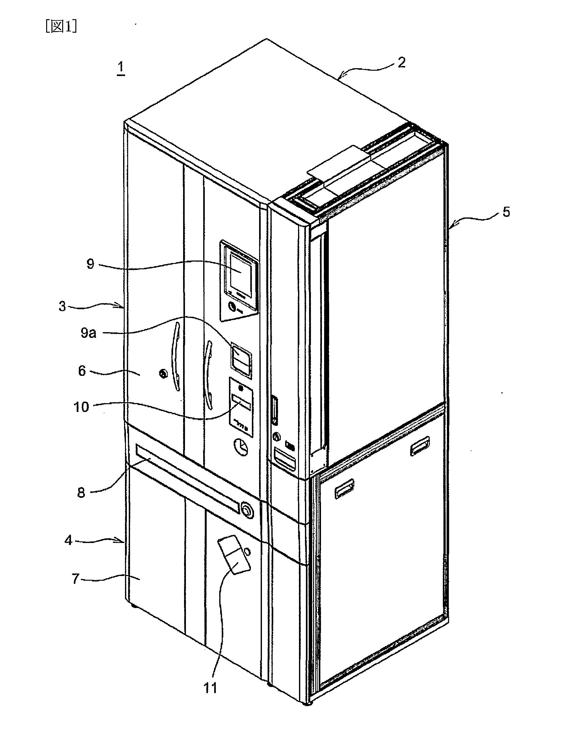
[0040]FIG. 1 shows a medicine delivering device 1 according to the present invention This medicine delivering device 1 comprises a device body 2, a medicine storage and removal unit 3, a medicine packaging unit 4, and a sub medicine storage and removal unit 5.
[0041] The device body 2 has a vertically long cubic shape, has a front upper portion and a front lower portion thereof provided with
doors 6 and 7 respectively, and has a central portion thereof drawably provided with a
manual medicine distributor 8. The upper door 6 is provided with an operation panel 9 and a journal printer 10 for printing medicine data and the like when the
manual medicine distributor 8 is used. The lower door 7 is provided with a
discharge port 11 for discharging a belt of medicine
package from the medicine packaging unit 4 The upper door 6 is further provided with a bar code reader 9a, so that, when a bar code written on an original box containing a medicine is held against this bar code reader 9a, a medicine cassette 13, to be described below, for this medicine moves to the front side of the door 6.
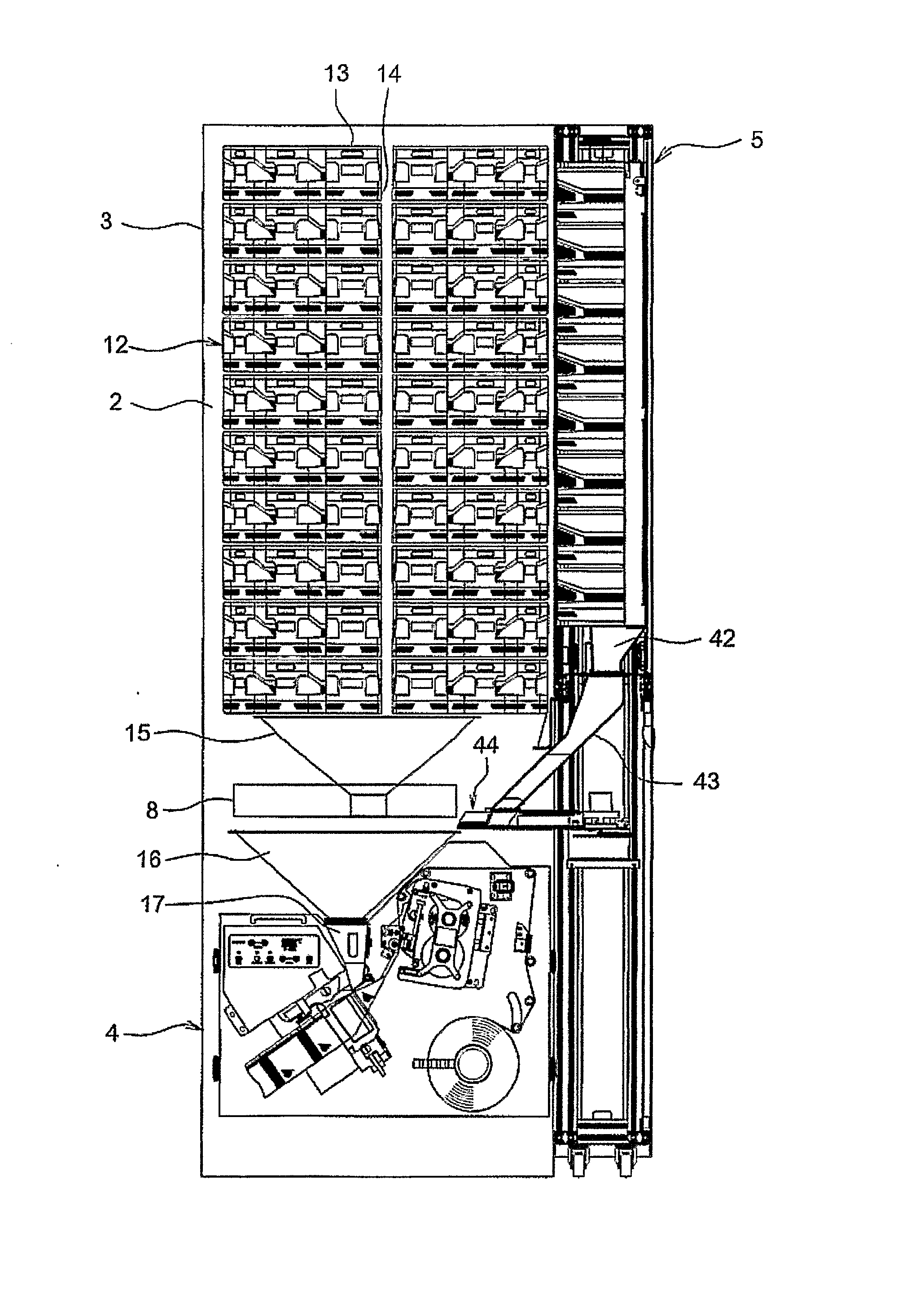
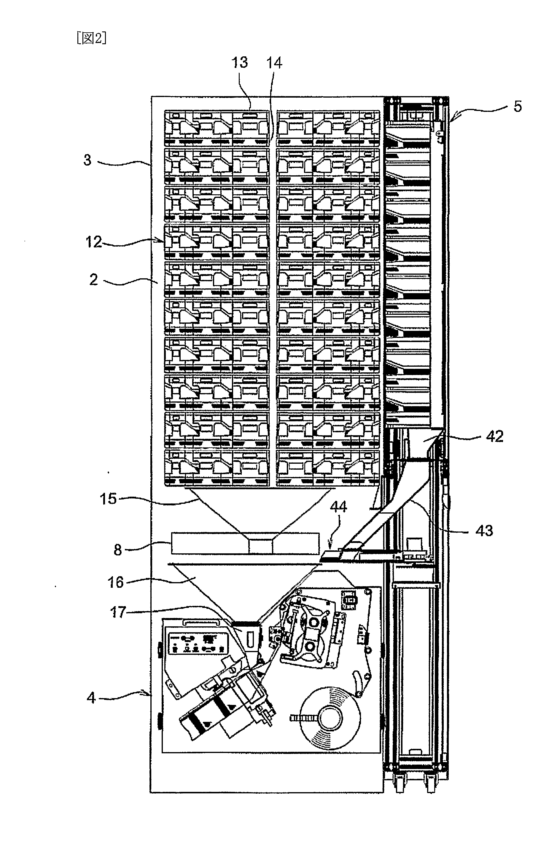
[0042] The medicine storage and removal unit 3 has, as shown in FIG. 2, has a drum 12 whose upper and lower ends are rotatably fitted to the device body 2. To the external surface of the drum 12, support stands 14, to which medicine cassettes 13 are fitted, are arranged circumferentially and also vertically in
multiple stages. The medicine cassette 13 stores the medicine therein and has a well-known structure that is capable of discharging medicines one by one thorough rotation of a rotor. The medicine discharged from the medicine cassette 13 is guided through a passage provided on the inner surface of the drum 12 to an upper collecting hopper 15 to be described below.
[0043] The medicine packaging unit 4 has on an upper portion thereof the upper collecting hopper 15, a lower collecting hopper 16, and a packaging hopper 17, as shown in FIG. 7 The upper collecting hopper 15 receives medicines taken out from the respective medicine cassettes 13 of the medicine storage and removal unit 3. The lower collecting hopper 16 consists of as shown in FIG. 4, a first hopper part 19 for receiving the medicine dropping from the
manual medicine distributor 8; and a second hopper part 20 for receiving the medicine dropping from the upper collecting hopper 15 and a medicine extruded from the sub-medicine storage and removal unit 5. The first hopper part 19 has as shown in FIG. 4, a
pyramid-like shape, and has therein a first divider plate 21 vertically oriented, second divider plates 22 provided on both sides of the first divider plate 21 in a tilted manner, and third divider plates 23 respectively formed between the second divider plates 22 and the side walls. These divider plates prevent a medicine dropping on the wall surface of the first hopper part 19 from bouncing, and thus prevent an increase in the drop time. The second hopper part 20 is provided on the outer side of the first hopper part 19, and has a common exit therewith. The packaging hopper 17 is detachably provided below the lower collecting hopper 16, and introduces medicine dropping from the lower collecting hopper 16 to packaging paper 26 to be described below. FIG. 11 shows the positional relationship among the lower collecting hopper 16, the manual medicine distributor 8 located thereabove, the upper collecting hopper 15, and a tablet extruding unit 44. The manual medicine distributor 8 is located above the first hopper part 19 of the lower collecting hopper 16 shown in FIG. 4. The exits of the upper collecting hopper 15 and the tablet extruding unit 44 are located above the second hopper part 20 shown in FIG. 4.
[0044] As shown in FIG. 3, in the right lower portion of the medicine packaging unit 4, a roll 25 of the packaging paper 26 is fitted. The packaging paper 26 rewound from the roll 25 is guided to a printer unit 27, where information, such as a
patient name, a medicine name,
dose date and time, and the like, is printed. The packaging paper 26 that has passed through the printer unit 27 with the predetermined information printed thereon is folded in half by a triangular plate 28 in such a manner as to open upward, and then receives the medicine discharged from the packaging hopper 17. The packaging paper 26 that has received the medicine is guided to a heat roller 29, where the packaging paper 26 is sealed vertically and horizontally, whereby the received medicine is sequentially received and reeled out obliquely downward as a packaging band 26′. The packaging band 26′ is conveyed obliquely upward by a conveyor, not shown, and discharged from the
discharge port 11 provided in the door. In the figure, in the left upper portion of the medicine packaging unit 4, there are provided the printer unit 27 and an operation panel 30 for adjusting the heat roller 29.

