Multi-layer light modulator

a light modulator and multi-layer technology, applied in non-linear optics, instruments, optics, etc., can solve the problems of preventing their widespread use, inadequate service life of these displays, and gas-based electrophoretic media being susceptible to the same types of problems, so as to reduce light loss

Active Publication Date: 2008-02-07
E INK CORPORATION
View PDF98 Cites 52 Cited by
  • Summary
  • Abstract
  • Description
  • Claims
  • Application Information

AI Technical Summary

Benefits of technology

[0028]Several different electrode arrangements may be used in the light modulators of the present invention. Typically, the light modulator will have two electrodes disposed on opposed sides of the plurality of variable transmission electro-optic layers. These may be the only electrodes present (i.e., there may not be any electrodes present between adjacent pairs of electro-optic layers), in which case the single pair of electrodes will control the optical state of all the electro-optic layers. Alternatively the light modulator may have at least one electrode between eac...

Problems solved by technology

Nevertheless, problems with the long-term image quality of these displays have prevented their widespread usage.
For example, particles that make up electrophoretic displays tend to settle, resulting in inadequate service-life for these displays.
Such gas-based electrophoretic media appear to be susceptible to the same types of problems due to particle settling as liquid-based electrophoretic media, when the media are used in an orientation which permits such settling, for example in a sign where the medium is disposed in a vertical plane.
Indeed, particle settling appears to be a more serious problem i...

Method used


Image

  • Multi-layer light modulator
  • Multi-layer light modulator
  • Multi-layer light modulator

Examples


Embodiment Construction

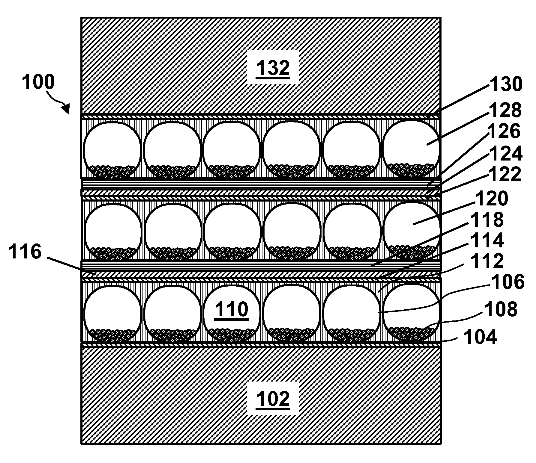
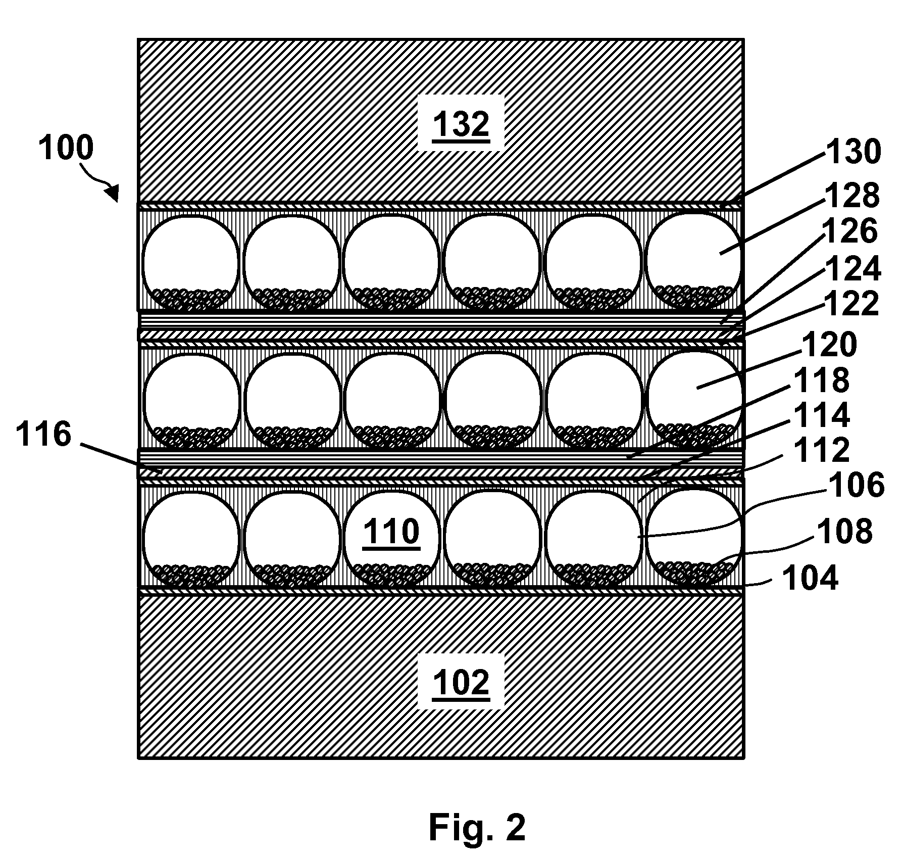
[0033]As indicated above, the present invention provides a light modulator comprising a plurality of discrete variable transmission electro-optic layers arranged so that light will pass successively through the plurality of layers. Typically the electro-optic or VT layers of the light modulator will be in the form of thin flat sheets having a width (in the plane of the sheet) much greater (say at least an order of magnitude greater) than the thickness of the sheet (perpendicular to the plane of the sheet). A stack of such thin sheets, preferably held together by optically clear adhesive between the sheets, can be produced in a form resembling a pane of glass, and thus suitable for use in a conventional window frame or similar glass-mounting device. Alternatively, such a stack of thin sheets can be mounted between two transparent, and typically rigid, sheets of glass, polymer or other material to produce a composite sheet which can readily be used in place of a pane of glass in a con...


PUM


Abstract

A light modulator comprises a plurality of discrete variable transmission electro-optic layers arranged so that light will pass successively through the plurality of layers; the light modulator has a higher transmission range than any of the individual electro-optic layers separately.

Description

REFERENCE TO RELATED APPLICATIONS[0001]This application claims benefit of Provisional Application Ser. No. 60 / 821,161, filed Aug. 2, 2006.[0002]This application is related to copending application Ser. No. 10 / 907,140, filed Mar. 22, 2005 (Publication No. 2005 / 0213191), which claims benefit of provisional Application Ser. No. 60 / 555,529, filed Mar. 23, 2004 and provisional Application Ser. No. 60 / 585,579, filed Jul. 7, 2004.[0003]This application is also related to U.S. Pat. No. 7,116,466, issued Oct. 3, 2006 on application Ser. No. 11 / 161,179, filed Jul. 26, 2005.[0004]This application is also related to copending application Ser. No. 11 / 162,188, filed Aug. 31, 2005 (Publication No. 2006 / 0038772), which claims benefit of provisional Application Ser. No. 60 / 605,761, filed Aug. 31, 2004. The aforementioned application Ser. No. 11 / 162,188 is also a continuation-in-part of the aforementioned application Ser. No. 10 / 907,140. The aforementioned application Ser. No. 11 / 162,188 is also a co...

Claims


Application Information

Patent Timeline
IPC IPC(8): G02F1/01G02F1/167G02F1/1675
CPCG02F1/167G02F1/1675
Inventor PAOLINI, RICHARD J.PATRY, SHAMUS FORD
Owner E INK CORPORATION
Why Eureka
Try Eureka