
Display device and method for fabricating the same

a technology for a display device and a manufacturing method, applied in the field of display devices, can solve the problems of low light efficiency and brightness, low and low brightness of the display device having only red, green and blue sub-pixels, and achieve the effect of high light transmissivity and brightness

Active Publication Date: 2008-02-07
SAMSUNG DISPLAY CO LTD
View PDF22 Cites 47 Cited by
  • Summary
  • Abstract
  • Description
  • Claims
  • Application Information

AI Technical Summary

Benefits of technology

The present invention introduces an innovative design for a display screen that has excellent clarity and can be easily viewed from different angles. This new technology offers higher levels of light transmission than traditional displays, resulting in brighter images. Additionally, this patented technique simplifies the manufacturing process compared to other methods.

Problems solved by technology

The technical problem addressed in this patent text is the presence of color filter remains or debris in a white sub-pixel region, which can cause color mixture and low light transmissivity, leading to low brightness in display devices with a color filter on array structure.

Method used


Image

  • Display device and method for fabricating the same
  • Display device and method for fabricating the same
  • Display device and method for fabricating the same

Examples


Embodiment Construction

[0019]The invention is described more fully hereinafter with reference to the accompanying drawings, in which embodiments of the invention are shown. This invention may, however, be embodied in many different forms and should not be construed as limited to the embodiments set forth herein. Rather, these embodiments are provided so that this disclosure is thorough, and will fully convey the scope of the invention to those skilled in the art. In the drawings, the size and relative size of layers and regions may be exaggerated for clarity. Like reference numerals in the drawings denote like elements.

[0020]It will be understood that when an element such as a layer, film, region or substrate is referred to as being “on”, “connected to”, or “coupled to” another element or layer, it can be directly on, directly connected to, or directly coupled to the other element or layer, or intervening elements or layers may also be present. In contrast, when en element is referred to as being “directl...


PUM


Abstract

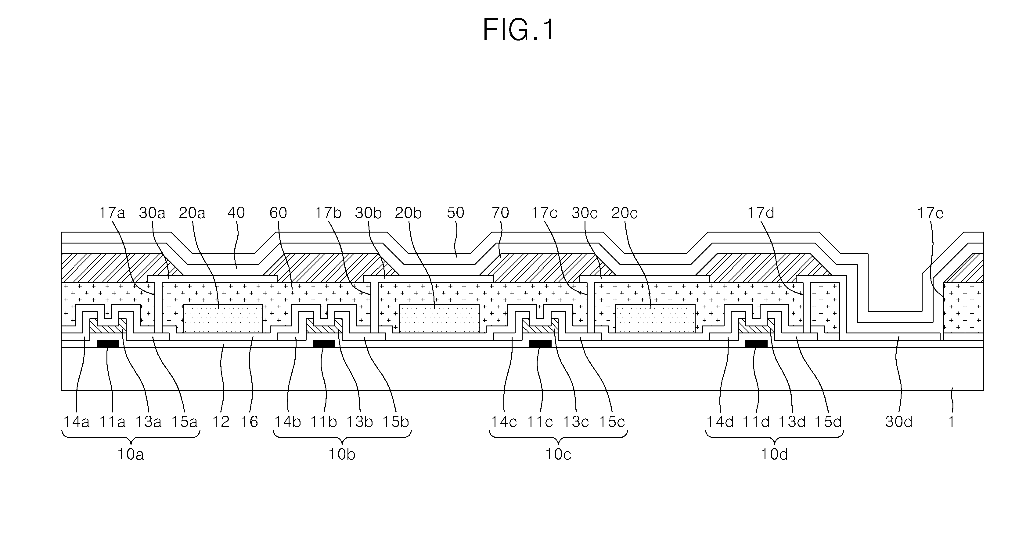
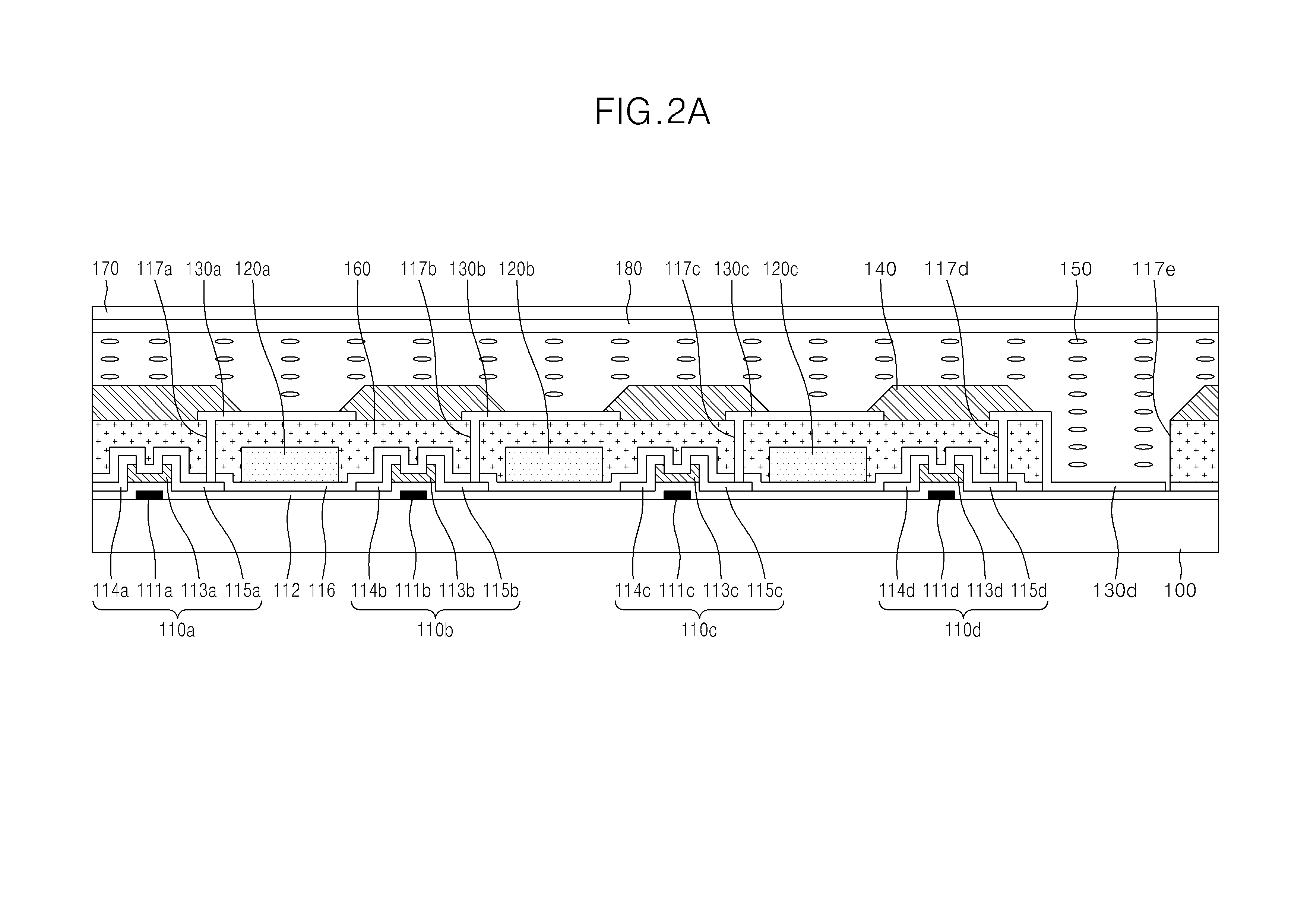
The present invention provides a display panel of a flat panel display device of a four-color structure in which color mixture may not occur in a white sub-pixel and a method for fabricating the same. The display device includes first, second, third, and fourth sub-pixels, and each sub-pixel includes a thin film transistor. A color filter is formed adjacent to the thin film transistor of each of the first, second, and third sub-pixels, a planarization layer is formed on the color filters, and a pixel electrode is connected to each thin film transistor.

Description


Claims


Application Information

Patent Timeline
Owner SAMSUNG DISPLAY CO LTD
Learn More