Supercharge Your Innovation With Domain-Expert AI Agents!

Servo architecture to minimize access time in optical disk drive

a technology of optical disk drive and servo, which is applied in the direction of information storage, instruments, data recording, etc., can solve the problems of affecting the performance of the optical disk drive, and the sensor either has poor resolution or is not always equipped with the dvd writer mechanism for minimal cost purposes, so as to simplify the dual-stage moving system and simple control architecture

Inactive Publication Date: 2008-02-07
ZHU FEIHONG
View PDF5 Cites 0 Cited by
  • Summary
  • Abstract
  • Description
  • Claims
  • Application Information

AI Technical Summary

Problems solved by technology

Access time consists of latency (the overhead of getting to the right place on the device and preparing to access it) and transfer time.
The address reading consumes a lot of seek time also.
Seek performance is degraded severely.
However, the sensor either has poor resolution or is not always equipped on DVD writer mechanism for minimal cost purpose.

Method used


Image

  • Servo architecture to minimize access time in optical disk drive
  • Servo architecture to minimize access time in optical disk drive
  • Servo architecture to minimize access time in optical disk drive

Examples


Embodiment Construction

[0034]Embodiments of the present invention will be discussed with reference to an optical disc drive. One skilled in the art will recognize that the present invention may also be applied to other data storage device, such as a magneto-optical disk drive

1. Mechanical Behavior Description with LHCE Definition

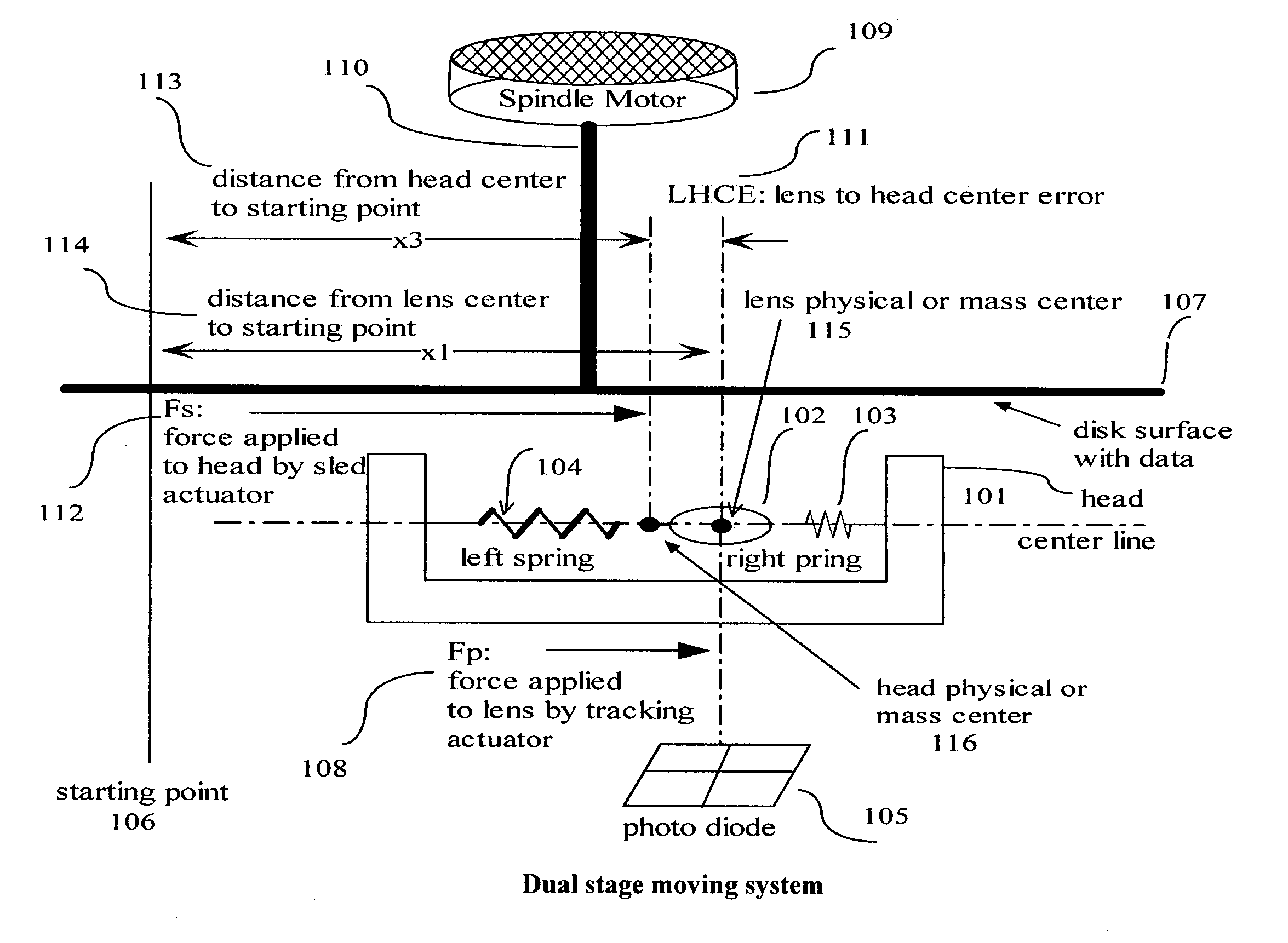
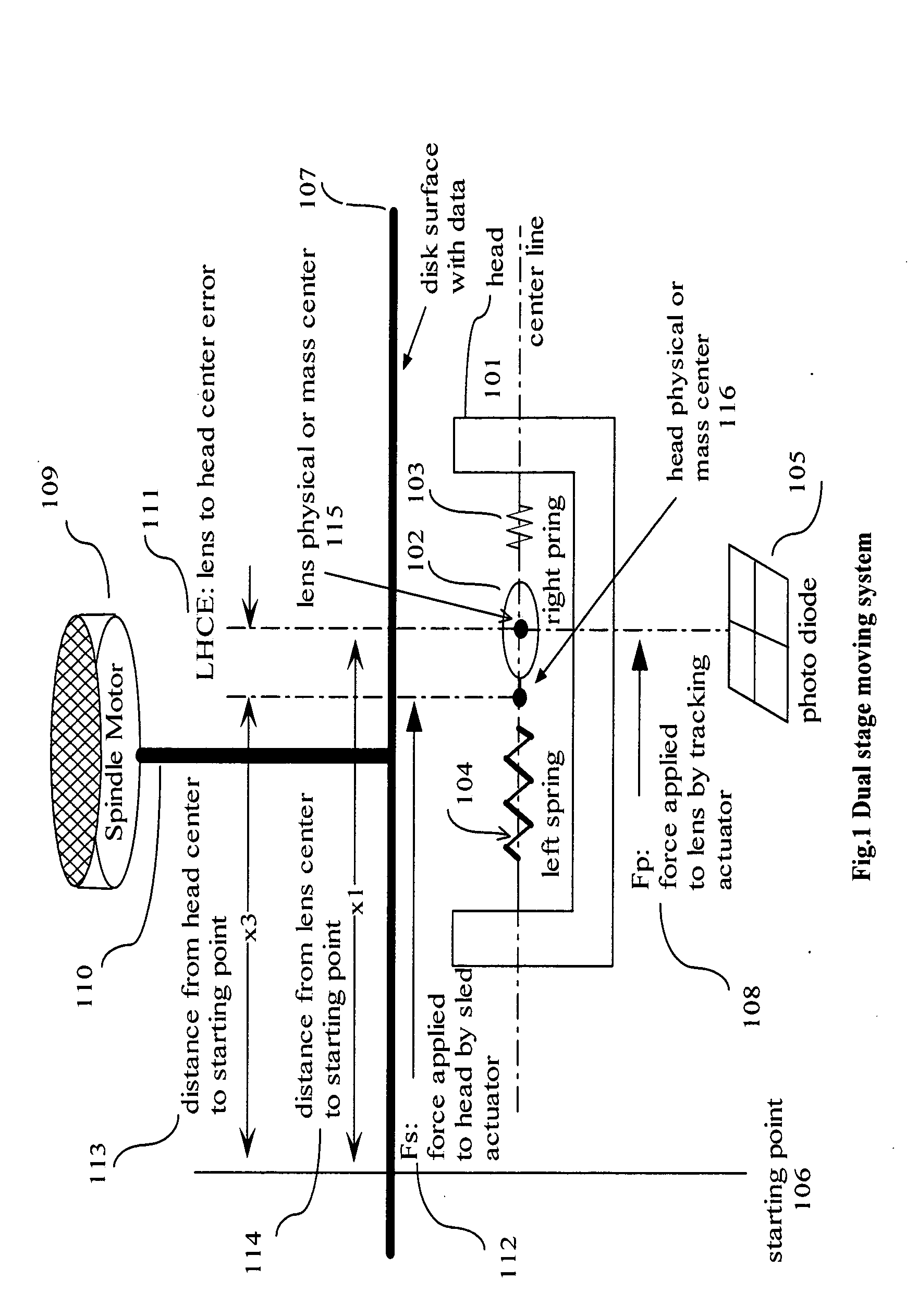
[0035]A dual stage moving system is presented in FIG. 1 for the application in optical storage field. A disk 107 is rotated by the spindle motor 109 through a spindle motor axis 110. Photo diode 105 receive reflected laser beam from disk surface where data can be allocated through lens 102. Lens 102 mounted on head 101 is connected through springs 104, 103. Force Fp 108 is applied to lens center 115 through tracking driver to position lens 102 and Force Fs 112 from sled driver is applied to head center 116 to position head 101. Starting point 106 is a common reference for the measurement of lens 102 and head 101 position. Starting point could be any where as long as the reference ...


PUM

PropertyMeasurementUnit
LHCE=distanceaaaaaaaaaa
forcesaaaaaaaaaa
forceaaaaaaaaaa

Abstract

An apparatus and method are disclosed to minimize seek time for dual stage actuator from both theoretical and real application viewpoints in optical disk drive application, where 1) a head mounted on a sled is positioned by a sled actuator; 2) A lens is mounted on the head with spring connection and optically coupled to a photo-sensor. A tracking actuator positions the lens with respect to tracks on the disk. The algorithms and designs include: a) dual stage mechanical models description from the real application consideration for track following and seek modes, respectively. The dual stage mechanical models describe the motion of lens and head driven by tracking and sled actuator in each mode. Meanwhile a simplified dual stage mechanical model with reduced parameters is given to decouple the link between lens and head; b) simplified model in track following mode and LHCE estimator design in track following mode. The LHCE is defined as error between head and lens physical centers in the dual stage mechanical moving direction. The LHCE estimator designs are based on simplified mechanical models in order to make head center following lens center movement in track following mode; c) a control architecture to position lens and sled based on LHCE estimator designs in seek modes; d) an architecture to switch design rules between tracking mode and seek mode. The method can also be applied to those cases where optical writer mechanism does not have LHCE sensor.

Description

CROSS-REFERENCE TO RELATED APPLICATIONS[0001]This application claims the benefit of provisional patent application Ser. No. 60 / 789,802, Filed Apr. 6, 2006 by the present inventor.FEDERALLY SPONSORED RESEARCH [0002]Not ApplicableSEQUENCE LISTING OR PROGRAM [0003]Not ApplicableBACKGROUND OF THE INVENTION [0004]1. Field of Invention[0005]This invention generally relates to servo architecture to move dual stage mechanism with minimal access time for optical storage device.[0006]2. Prior Art1. Related Application Environment of the Invention[0007]On the compact optical disk, data is stored in the form of pits and land patterned in a radial track. The track is formed in one spiral line extending from the inner radius of the disk to the outer edge. A pit is a location on the disk where data has been recorded by creating a depression in the surface of the disk with respect to the lands. The lands are the areas between the pits in the tangential direction. The reflectivity of the pits is les...

Claims


Application Information

Patent Timeline
Patent Type & Authority Applications(United States)
IPC IPC(8): G11B7/00
CPCG11B7/0929G11B7/08582
Inventor ZHU, FEIHONG
Owner ZHU FEIHONG
Features
  • R&D
  • Intellectual Property
  • Life Sciences
  • Materials
  • Tech Scout
  • Unparalleled Data Quality
  • Higher Quality Content
  • 60% Fewer Hallucinations
Learn More