
Flexible optical waveguide film, optical transceiver module, multi-channel optical transceiver module, and method of manufacturing flexible optical waveguide film

a technology of flexible optical waveguide and optical waveguide film, which is applied in the direction of optical waveguide light guide, optical elements, optical waveguides, etc., can solve the problems of item (1), cost increase, and accuracy of the diameter of the core obtained by the method

Inactive Publication Date: 2008-02-07
FUJIFILM BUSINESS INNOVATION CORP
View PDF20 Cites 22 Cited by
  • Summary
  • Abstract
  • Description
  • Claims
  • Application Information

AI Technical Summary

Problems solved by technology

However, the selective polymerization method of the above item (1) has a problem when films are combined.
The RIE method of the above item (2) and the direct exposure method of the above item (3) result in a cost increase because a photolithographic process is used.
The injection molding method of the above item (4) has a problem with the accuracy of the diameter of a core obtained by the method.
The photo-bleaching method of the above item (5) has a problem in that a sufficient difference cannot be obtained between the refractive indices of a core layer and a clad layer.
Although the RIE method of the above item (2) and the direct exposure method of the above item (3) may be regarded as practical methods providing high performance, they have a problem with manufacturing costs as mentioned above.
Any of the manufacturing methods of the above items (1) to (5) is practically unsuitable for the formation of a polymer optical waveguide on a plastic substrate which has a great area and which is flexible.

Method used


Image

  • Flexible optical waveguide film, optical transceiver module, multi-channel optical transceiver module, and method of manufacturing flexible optical waveguide film
  • Flexible optical waveguide film, optical transceiver module, multi-channel optical transceiver module, and method of manufacturing flexible optical waveguide film
  • Flexible optical waveguide film, optical transceiver module, multi-channel optical transceiver module, and method of manufacturing flexible optical waveguide film

Examples


first exemplary embodiment

[First Exemplary Embodiment of the Invention]

(Configuration of Polymer Optical Waveguide Film)

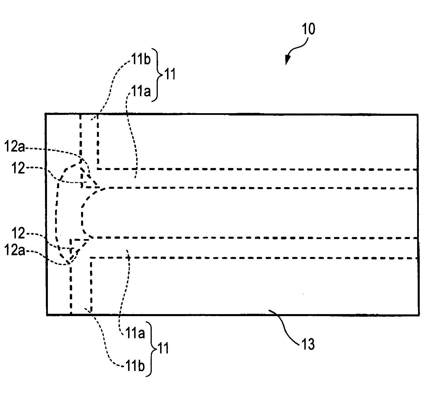
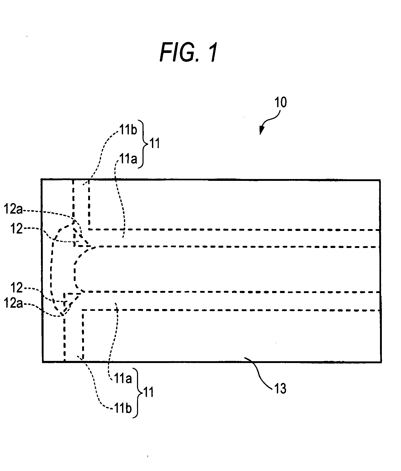
[0019]FIG. 1 is a plan view of a polymer optical waveguide film representing a first exemplary embodiment of the invention schematically showing an example of a configuration of the same.

[0020]In FIG. 1, reference numeral 10 represents a polymer optical waveguide film. Referring to the basic configuration of the polymer optical waveguide film 10, as shown in FIG. 1, it is constituted by a planar flexible optical waveguide film having two waveguide cores 11, 11 and a clad 13 surrounding the periphery of the two waveguide cores 11. In the illustrated example, the polymer optical waveguide film 10 includes the two waveguide cores 11, 11 constituted by a pair of first cores 11a, 11a extending the lengthwise direction of the film and a pair of second cores 11b, 11b extending orthogonally to the first cores 11a toward widthwise end faces of the film that are opposite to each other, optical path c...

second exemplary embodiment

[Second Exemplary Embodiment of the Invention]

(Configuration of Polymer Optical Waveguide Film)

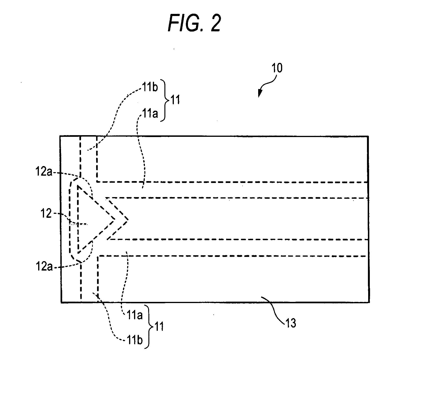
[0023]FIG. 2 is a plan view of a polymer optical waveguide film in a second exemplary embodiment of the invention schematically showing an example of a configuration of the same. In the same figure, members substantially identical to those in the first exemplary embodiment of the invention are indicated by like member names and reference numerals. Therefore, detailed description will be omitted for such members.

[0024]FIG. 2 is significantly different from the first exemplary embodiment of the invention in that the second cores 11b extending toward the end faces in the widthwise direction of the film from one end of the respective first cores 11a are formed on the same straight line and in that a single optical path converting part 12 is formed in a position corresponding to the connecting part which connects the intersections between the first and second cores 11a and 11b.

[0025]The polyme...

third exemplary embodiment

[Third Exemplary Embodiment of the Invention]

(Configuration of Transceiver Module for Two-Way Communication]

[0074]FIG. 3 is a plan view of a transceiver module representing a third exemplary embodiment of the invention schematically showing an example of a configuration of the same. In FIG. 3, members substantially identical to members in the first and second exemplary embodiments of the invention are indicated by like member designations and reference numerals. Therefore, detailed description will be omitted for those members.

[0075]In FIG. 3, reference numeral 20 represents a transceiver module for two-way communication. Referring to a basic configuration of the transceiver module, as shown in FIG. 3, the module includes two waveguide cores 11, 11 having air voids constituting optical path converting parts 12 at both ends of a polymer optical waveguide film 10 formed by constituent members substantially identical to those in the second exemplary embodiment of the invention and ligh...


PUM


Abstract

A flexible optical waveguide film comprises: two waveguide cores; and a clad surrounding the two waveguide core, wherein a light entrance / exit part is disposed at one end of each of the two waveguide cores, the waveguide film having an optical path converting part comprising an air void located inside the waveguide film, and a light entrance / exit end face of the light entrance / exit part is a plane surface facing an optical path converting surface of the optical path converting part, the optical path converting surface being an interface defining the air void.

Description

CROSS-REFERENCE TO RELATED APPLICATIONS[0001]This application is based on and claims priority under 35 USC 119 from Japanese Patent Application No. 2006-212282 filed Aug. 3, 2006.BACKGROUND[0002](i) Technical Field[0003]The present invention relates to a flexible optical waveguide film, an optical transceiver module, a multi-channel optical transceiver module, and a method of manufacturing a flexible optical waveguide film. Particularly, the invention relates to a flexible optical waveguide film, an optical transceiver module, and a multi-channel optical transceiver module having a low profile or size and a method of manufacturing a flexible optical waveguide film which allows manufacturing steps to be simplified.[0004](ii) Related Art[0005]Various methods for manufacturing a polymer optical waveguide have been proposed in the related art including, for example:[0006](1) a method in which films are impregnated with a monomer and in which the films are combined with the refractive in...

Claims


Application Information

Patent Timeline
Patent Type & Authority Applications(United States)
IPC IPC(8): G02B6/10H04B10/00G02B6/122G02B6/13G02B6/42
CPCG02B6/10G02B6/4214G02B6/138G02B6/1221
Inventor OHTSU, SHIGEMISUZUKI, TOSHIHIKOFUJII, AKIRAYATSUDA, KAZUTOSHISHIMIZU, KEISHIAKUTSU, EIICHI
Owner FUJIFILM BUSINESS INNOVATION CORP
Learn More