Passive optical network optical time-domain reflectometry

a technology of optical time-domain reflectometry and optical network, applied in the field of passive optical network, can solve the problems of affecting the use of passive splitters, requiring significant periodic maintenance, and active components subject to failure and performance degradation

Inactive Publication Date: 2008-02-07
ALCATEL LUCENT SAS
View PDF4 Cites 64 Cited by
  • Summary
  • Abstract
  • Description
  • Claims
  • Application Information

AI Technical Summary

Problems solved by technology

In addition to requiring power, active components are subject to failure and performance degradation over time, and may require significant periodic maintenance.
While an OTDR can successfully be used to troubleshoot many types of optical networks, signal losses from the passive splitters hamper its use in a typical PON of the type that provides video, voice, Internet service, etc., from a service provider to subscribers.
This arrangement does not work well because the fiber and splitters can contribute a total signal loss that can exceed the useful dynamic range of OTDR 10.
It is generally not possible to take useful OTDR measurements where the signal loss is 50 dB.

Method used


Image

  • Passive optical network optical time-domain reflectometry
  • Passive optical network optical time-domain reflectometry
  • Passive optical network optical time-domain reflectometry

Examples


Embodiment Construction

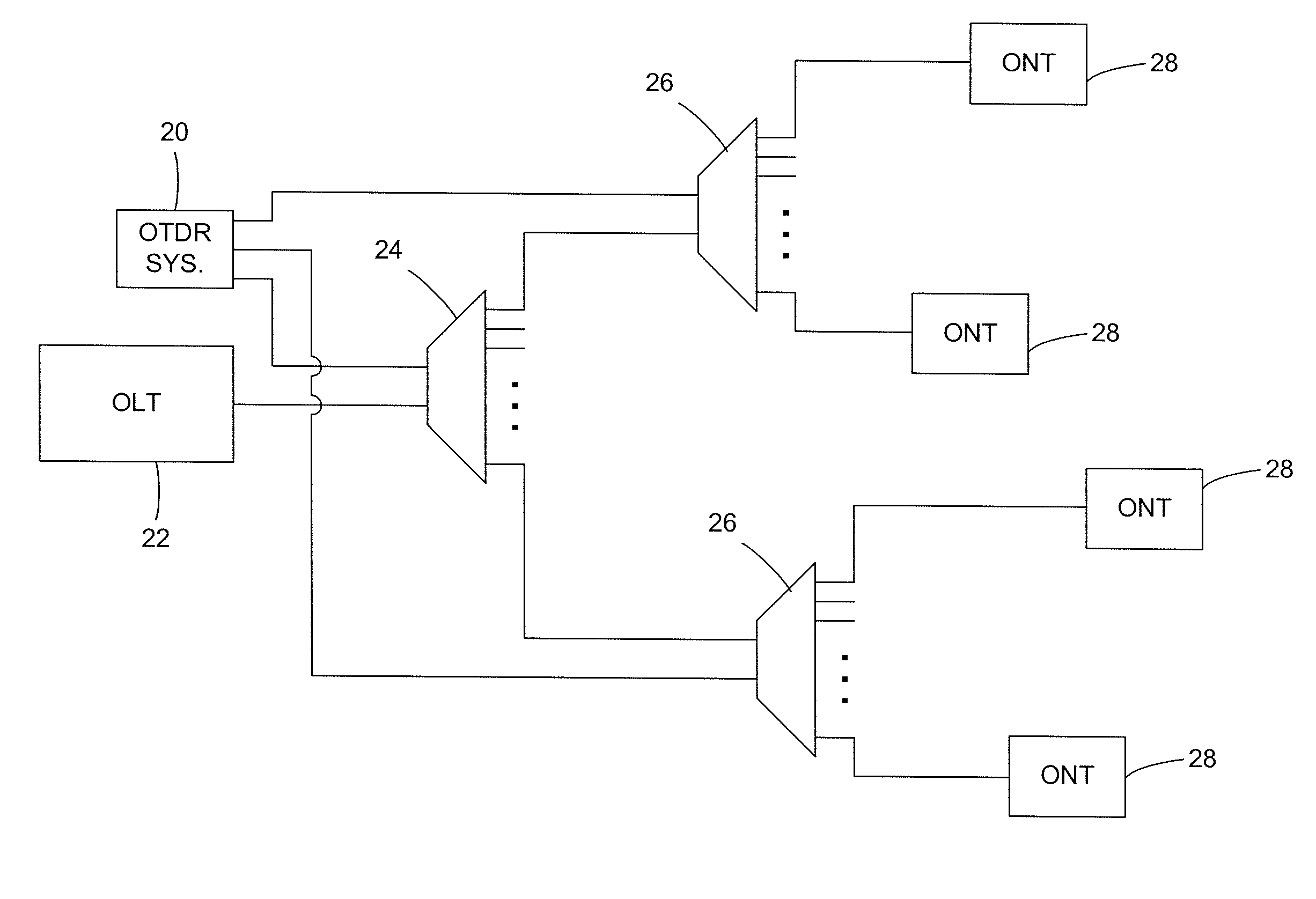
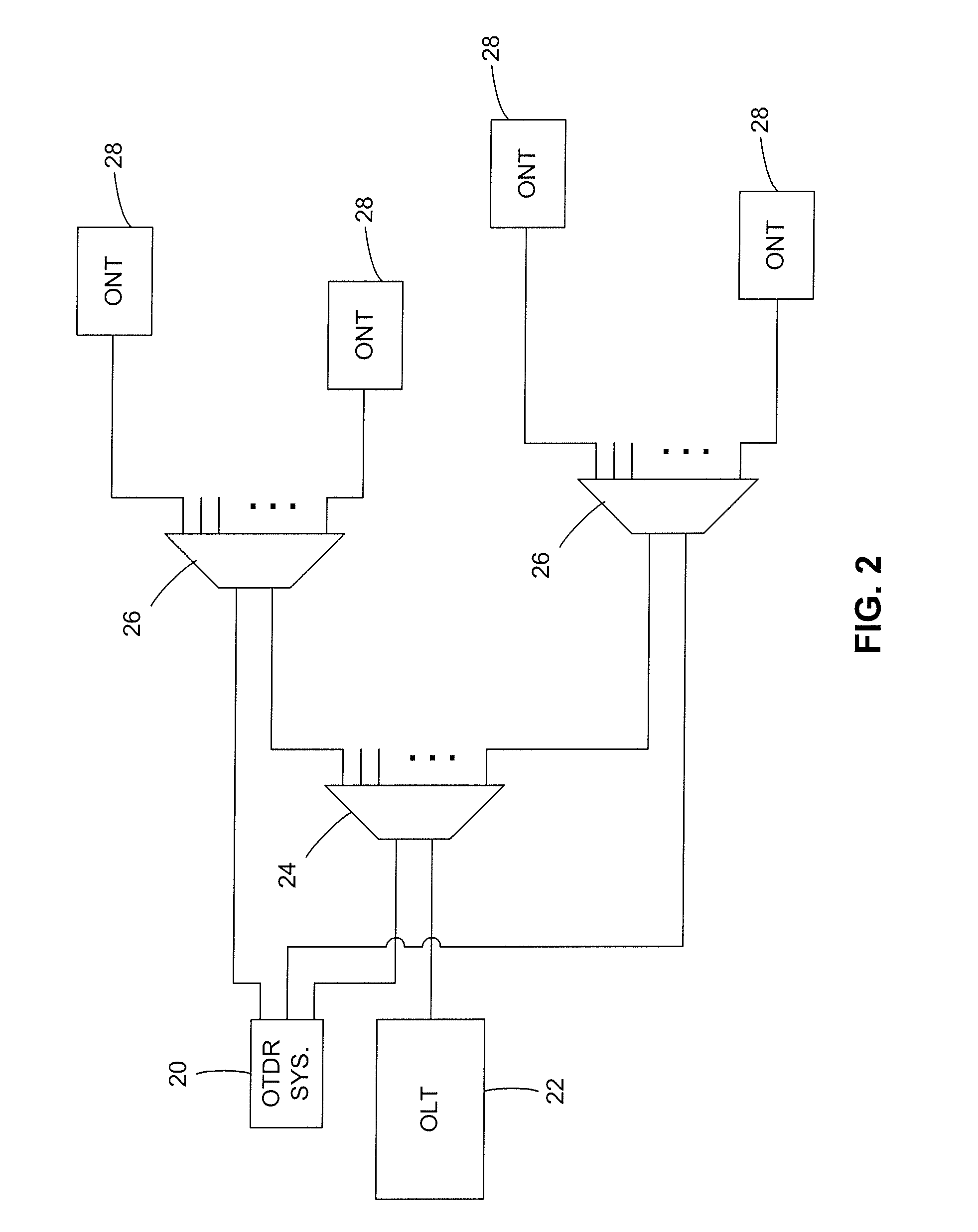
[0017]As illustrated in FIG. 2, in an exemplary embodiment of the invention, an Optical Time-Domain Reflectometer (OTDR) system 20 has a plurality of connections to a passive optical network (PON). Although in the illustrated embodiment OTDR system 20 provides a plurality of connections that can be selectably operated (i.e., selected and operated independently of one another), in other embodiments a splitter or other suitable passive or active device (not shown) can be used to multiplex or switch a single OTDR output onto a plurality of fibers, including a manually operated device such as a switch or patch panel. The PON includes an optical line terminator (OLT) 22, a first-level (2:8) splitter 24, eight second-level (2:8) splitters 26, and 64 optical network terminals (ONTs) 28. Note that there is a cascade arrangement between first-level splitter 24 and each of second-level splitters 26. The number of ONTs 28 and splitters 24 and 26 and their arrangement in this embodiment is for ...


PUM


Abstract

Optical Time-Domain Reflectometer (OTDR) troubleshooting of a passive optical network (PON) can be enhanced by deploying cascaded splitters, at least some of which have multiple inputs. That is, at least some of the splitters in the PON have not only a first input coupleable to the optical line terminator (OLT) or output of another splitter but also a second input directly coupleable to an Optical Time-Domain Reflectometer (OTDR). Optical time-delay reflectometry can be performed upon a selected portion or segment of the PON by selecting a splitter and transmitting an optical test signal from the OTDR directly to the input of the selected splitter and analyzing the reflected signal.

Description

BACKGROUND OF THE INVENTION[0001]1. Field of the Invention[0002]The present invention relates generally to passive optical networks (PONs) and, more specifically, to troubleshooting a PON using an Optical Time-Domain Reflectometer (OTDR) or other optical instrument.[0003]2. Description of the Related Art[0004]Most digital telecommunications networks (i.e., networks that facilitate the communication of data, voice, video, etc., between parties or between a content distribution service and subscribers) typically comprise active components, such as repeaters, relays and other such devices that consume power, in the path between a central office (or exchange, as its sometimes referred to) and a subscriber. In addition to requiring power, active components are subject to failure and performance degradation over time, and may require significant periodic maintenance. The passive optical network (PON) has been developed to overcome some of these deficiencies. The essence of a PON is that n...

Claims


Application Information

Patent Timeline
Patent Type & Authority Applications(United States)
IPC IPC(8): H04J14/00
CPCH04J3/1694H04B10/071
Inventor SMITH, JOSEPH LEEGRANGER, ALAIN
Owner ALCATEL LUCENT SAS
Why Eureka
Try Eureka