Multiplexed graphics architecture for graphics power management

a graphics power management and multi-processing technology, applied in the direction of instruments, power supply for data processing, liquid/fluent solid measurement, etc., can solve the problems of reducing battery life, significantly increasing power consumption, and increasing the cost of graphics capabilities

Active Publication Date: 2008-02-07
APPLE INC
View PDF12 Cites 139 Cited by
  • Summary
  • Abstract
  • Description
  • Claims
  • Application Information

AI Technical Summary

Benefits of technology

[0015]In some embodiments, the program module further includes instructions for an application, and the decoupling and coupling are configured to occur while the operating system and the application are running. Moreover, in some embodiments the program module furth

Problems solved by technology

Unfortunately, there are costs associated with these increased graphics capabilities.
In particular, these capabilities can significantly increase power consumption.
As a consequence, many computer systems and portable devices devote a significant amount of their power to support these GPUs, which decreases battery life and causes heat dissipation problems.
Furthermore, existing approaches to managing such power consumption issues are often inadequate.
Unfortunately, many existing GPUs are not configur

Method used


Image

  • Multiplexed graphics architecture for graphics power management
  • Multiplexed graphics architecture for graphics power management
  • Multiplexed graphics architecture for graphics power management

Examples


embodiment 700

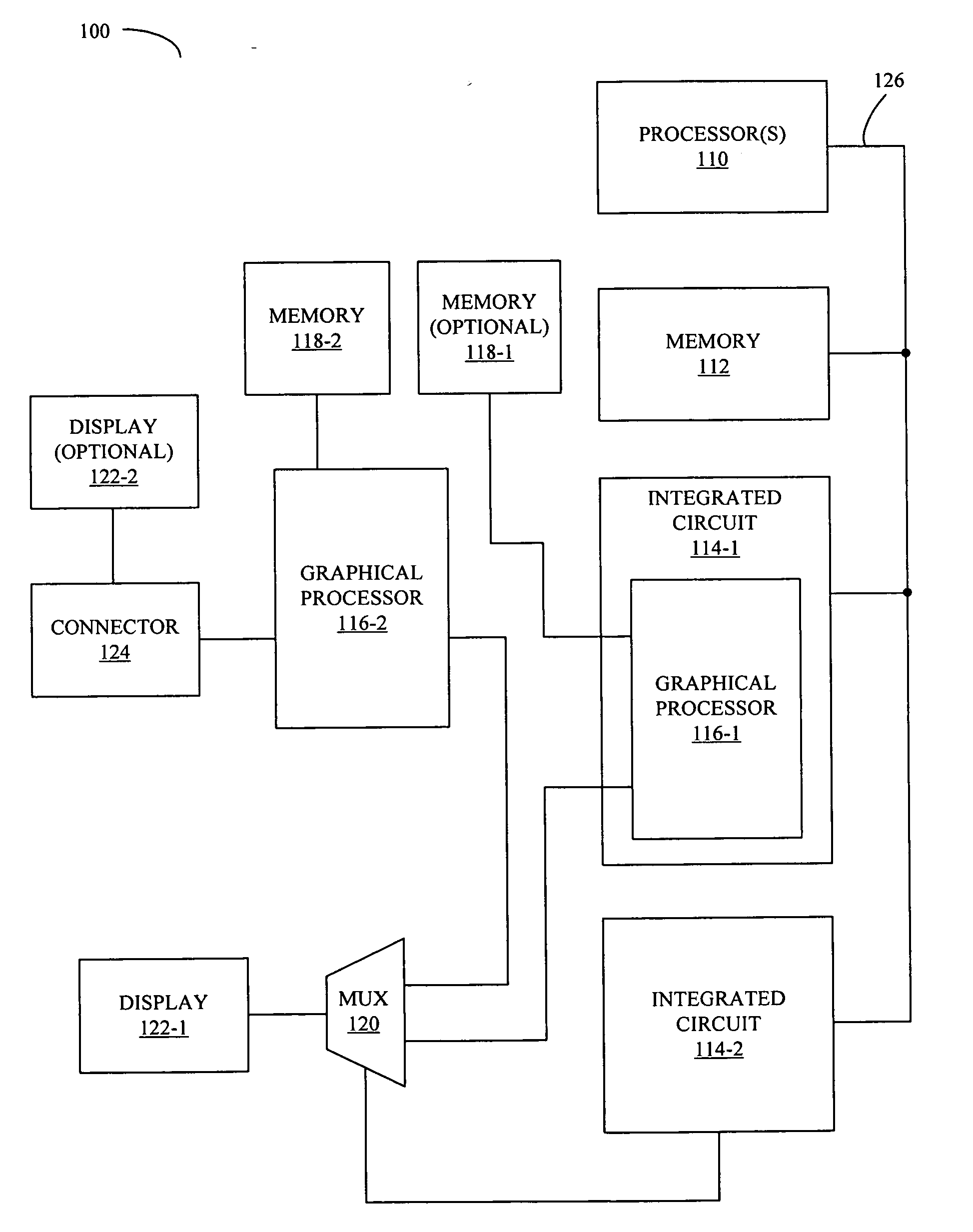
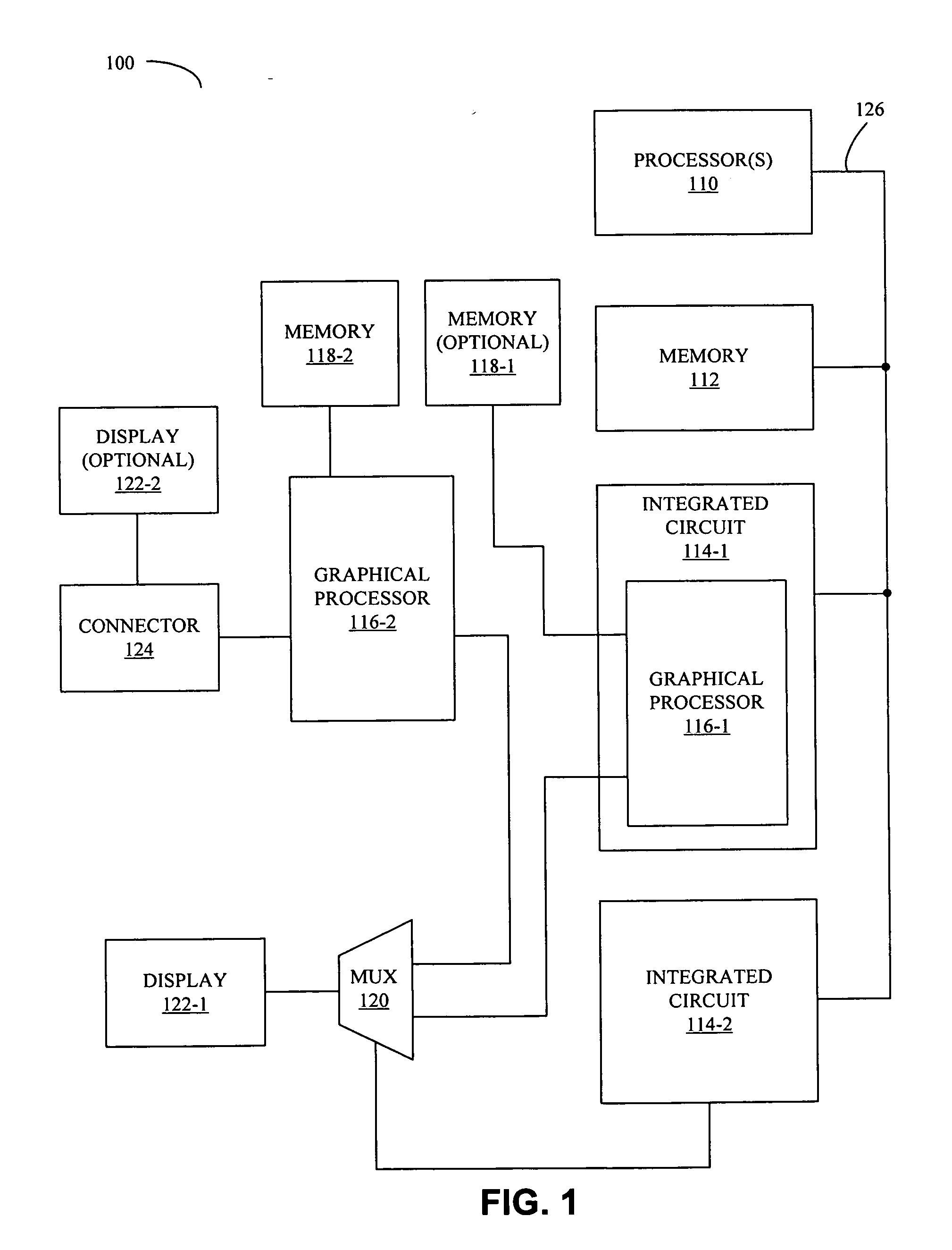
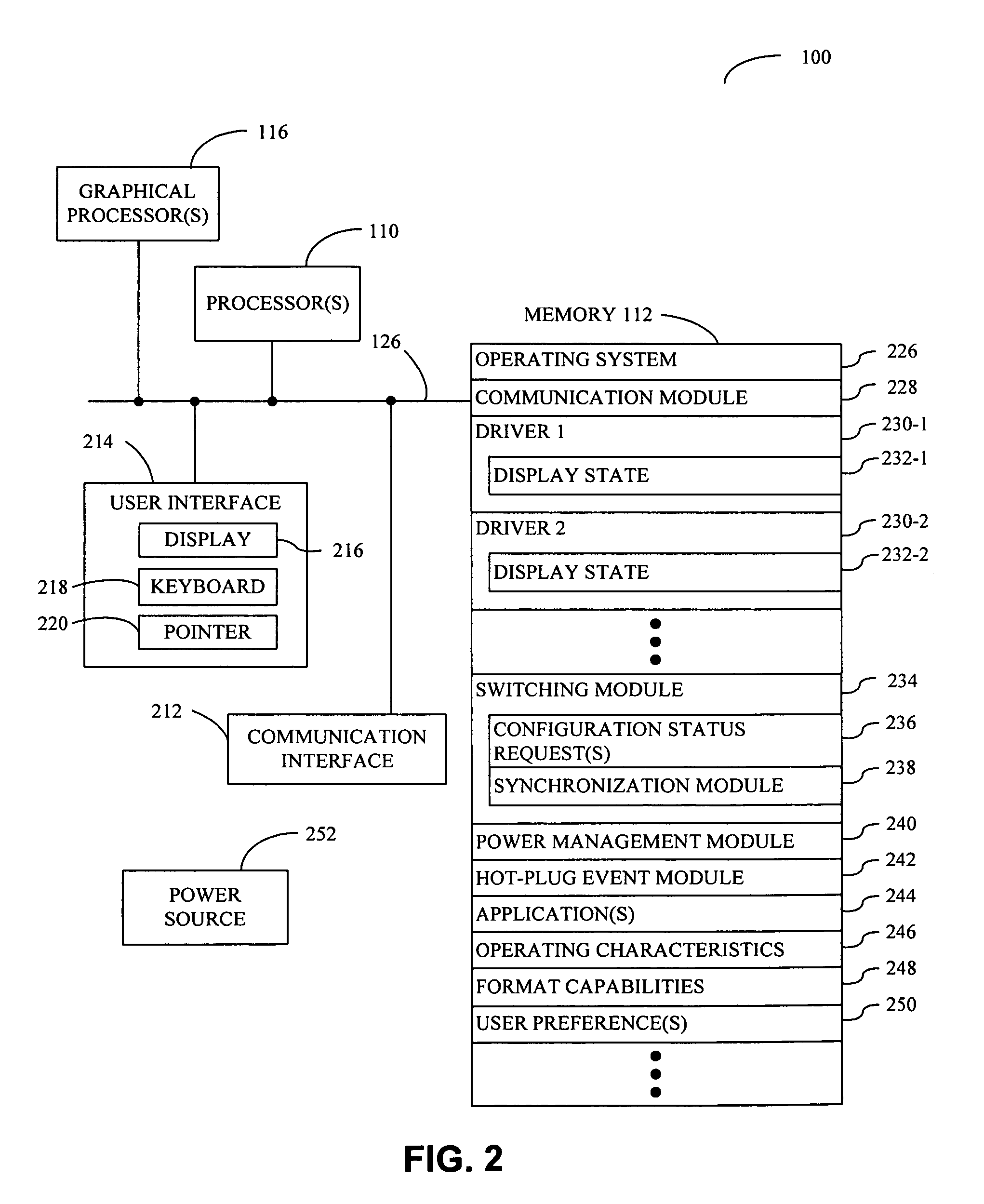
[0071]Once the operating system is notified of the change in GPU configuration, it then rebuilds the display device in the operating system kernel using the new display environment (including the new GPU and its corresponding display driver). This is illustrated in embodiment 700. After starting (710), the changed frame buffers are rebuilt (712). Then the cross-device state (i.e., the stored display state) is restored (714) and, in embodiments without synchronization, the fade level of the backlight is restored (716). The process 700 then ends (718).

embodiment 800

[0072]We now discuss adjusting backlight of the display in embodiments that do not include synchronization. FIG. 8 provides a block diagram illustrating a display signal timing sequence in accordance with an embodiment 800 of the present invention. After the GPU configuration has been changed, panel power 810 is ramped up and panel data 812 are provided by the new GPU. Once the screen is redrawn, panel backlight 814 is increased. If the GPU configuration is to be changed at a later time, the various signals can be decreased or ramped down in reverse order.

[0073]In some embodiments, the old GPU blanks the display (displays black or another color, turns the backlight off, and / or turns the display off) prior to the dynamic switching. While this approach may not be smooth or continuous (the switching may be visible to the user), it can be done in a fraction of a second. In other embodiments, the dynamic switching may be performed over a longer time interval. For example, it may be disgu...


PUM


Abstract

A computer system includes a processor, a memory, first and second graphical processors that have different operating characteristics, a switching mechanism coupled to the graphical processors, and a display coupled to the switching mechanism. The switching mechanism is configured to couple a given graphical processor to the display, and is initially configured to couple the first graphical processor to the display. Furthermore, a program module, which is stored in the memory and configured to be executed by the processor, is configured to change a configuration of the switching mechanism thereby decoupling the first graphical processor from the display and coupling the second graphical processor to the display. Note that the changing of the configuration and switching module operations are configured to occur while an operating system is running and are based on the operating condition of the computer system.

Description

BACKGROUND[0001]1. Field of the Invention[0002]The present invention relates to power management techniques for computer systems. More specifically, the present invention relates to electronic circuits, processes, and software that facilitate switching between graphics processing units for power management purposes.[0003]2. Related Art[0004]Power management is already critically important for many electronic devices. For example, portable devices such as laptop computers (notebook PCs), cellular telephones, and personal digital assistants need to conserve power in order to operate for any length of time on battery power. Power management is also important for computer systems that directly or indirectly operate on A / C power to meet strict power-usage requirements for ENERGY STAR qualification.[0005]At the same time, many of these electronic devices are beginning to incorporate high-resolution, high-power graphics technology. Rapid developments in this area have led to significant ad...

Claims


Application Information

Patent Timeline
IPC IPC(8): G06F1/00
CPCG06F1/3218G06F1/3203
Inventor HENDRY, IAN C.HOWARD, BRIAN D.
Owner APPLE INC
Why Eureka
Try Eureka