Sheet conveying apparatus and image forming apparatus

a conveying apparatus and forming apparatus technology, applied in the direction of electrical apparatus, thin material processing, article separation, etc., can solve the problems of color tone variation on each sheet, difficulty in reducing an amount of skew, and misregistration of dot forming of each color, so as to reduce the size of the conveying apparatus without reducing productivity

Inactive Publication Date: 2008-02-14
CANON KK
View PDF20 Cites 9 Cited by
  • Summary
  • Abstract
  • Description
  • Claims
  • Application Information

AI Technical Summary

Benefits of technology

[0020]The present invention is directed to a sheet conveying apparatus which contributes to downsizing an image forming apparatus without reducing productivity.

Problems solved by technology

It is difficult to decrease an amount of skew by electrically correcting the skew.
However, in a case of a color image forming apparatus that lays three or four colors to form an image, if the image is to be inclined in each sheet, dot forming of each color shows misregistration so that color tone varies on each sheet.
Further, since time is required to calculate the amount of inclination of the image, productivity is greatly decreased.
However, in a sheet conveying apparatus employing the first or the second system, since the skew is corrected by using a stiffness of the sheet, it is difficult to correct skew of a thin sheet.
That is, when a thin sheet abuts a nip of the registration roller pair or when a side edge of the sheet abuts the reference wall, the sheet is bent, which results in creases.
Consequently, the skew cannot be reliably corrected.
Additionally, when in an attempt to reduce the size of such an image forming apparatus, a sensor which detects the amount of skew is placed upstream of the skew correction roller pairs so that the skew is corrected by the skew correction roller pairs directly after the amount of skew is detected, the following problem arises.
Namely, in this case, the skew cannot be corrected until a deflection is formed between the skew correction roller pairs and the conveyance roller pairs.
Therefore, the apparatus cannot be sufficiently down-sized.
As described above, the conventional sheet conveying apparatus employing the third configuration has a problem in productivity as well as downsizing since an image forming apparatus having such sheet conveying apparatus requires a longer space between the skew correction roller pairs and apparatuses located downstream of the skew correction roller pairs.

Method used


Image

  • Sheet conveying apparatus and image forming apparatus
  • Sheet conveying apparatus and image forming apparatus
  • Sheet conveying apparatus and image forming apparatus

Examples


Embodiment Construction

[0029]Various exemplary embodiments, features, and aspects of the invention will be described in detail below with reference to the drawings.

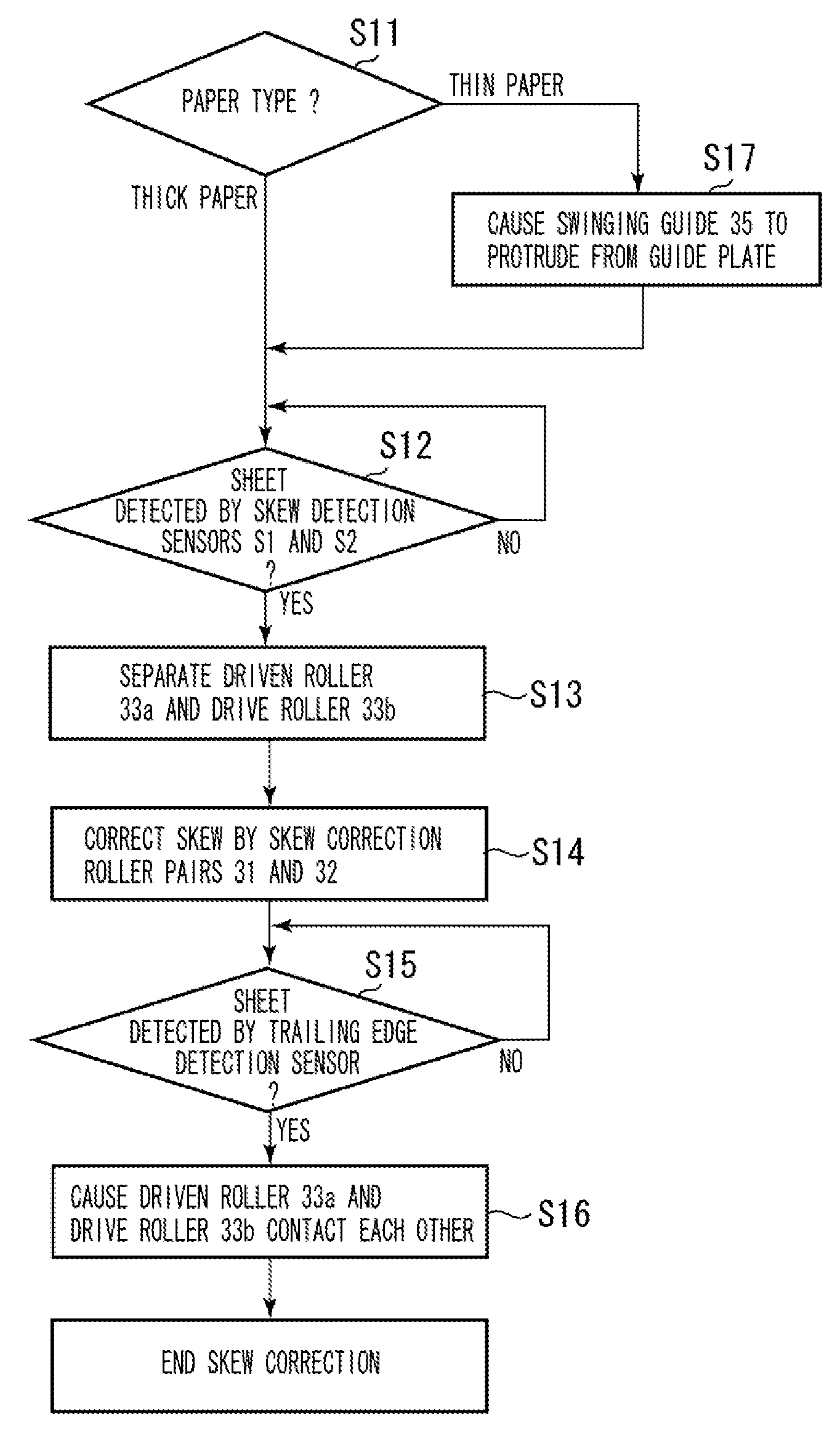
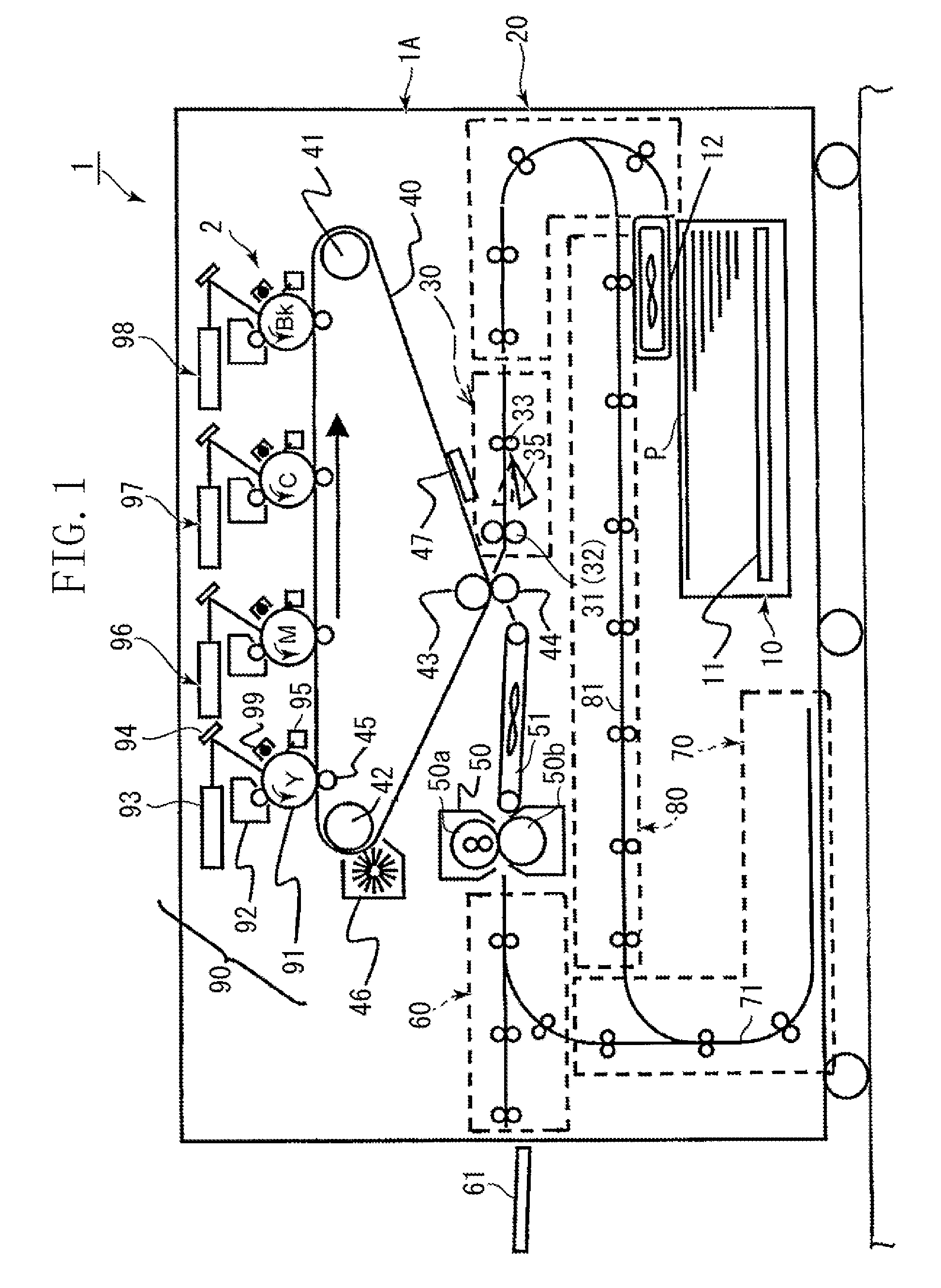
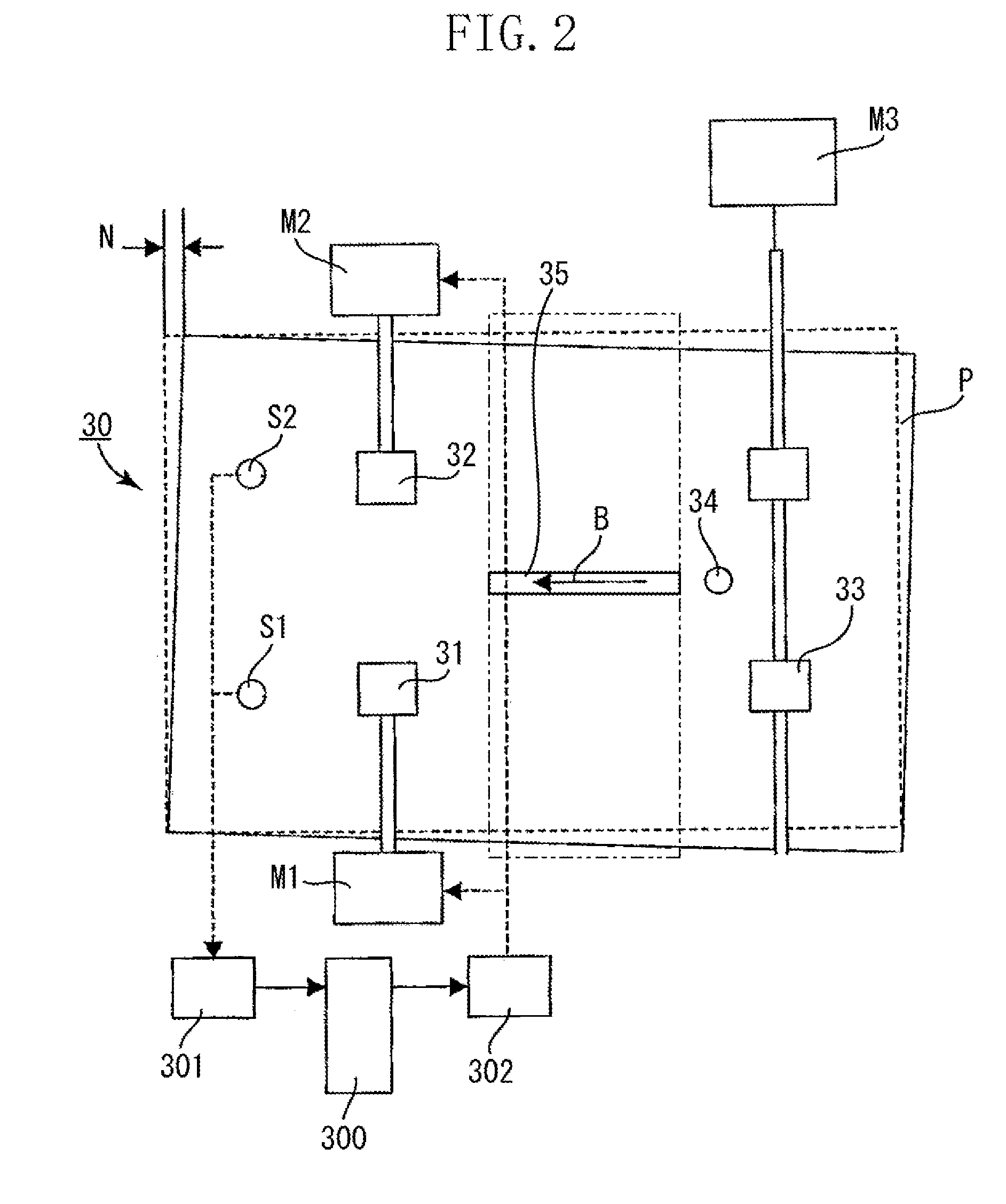
[0030]FIG. 1 is a cross-sectional view of an image forming apparatus 1 taken in a sheet conveyance direction according to an exemplary embodiment of the present invention. The image forming apparatus 1 forms an image on a sheet. If a sheet is skewed before an image is formed, the image forming apparatus 1 corrects the skew by a registration unit 30 that serves as a sheet conveying apparatus, and conveys the skew-corrected sheet to an image forming unit 2 where the image is formed. The image forming apparatus 1 can be a printer, a fax machine, a copying machine, or a multifunction peripheral having all such functions.

[0031]The image forming apparatus 1 has, in an apparatus body 1A, the image forming unit 2 including four image forming stations, an intermediate transfer belt 40, and a secondary transfer outer roller 44.

[0032]The four image formin...


PUM

PropertyMeasurementUnit
stiffnessaaaaaaaaaa
photosensitiveaaaaaaaaaa
colorsaaaaaaaaaa

Abstract

A registration unit includes a skew correction roller pair configured to rotate a sheet conveyed from a conveyance roller pair and to correct skew of the sheet. The registration unit sheet further includes a projectable swinging guide arranged between the conveyance roller pair and the skew correction roller pair to deflect the sheet. The skew correction roller pair corrects the skew of the sheet deflected by the swinging guide.

Description

BACKGROUND OF THE INVENTION[0001]1. Field of the Invention[0002]The present invention relates to a sheet conveying apparatus configured to convey a sheet while correcting skew of the sheet and an image forming apparatus configured to form an image on the sheet having the skew corrected, which includes the sheet conveying apparatus.[0003]2. Description of the Related Art[0004]Conventionally, electrophotography, offset printing, and inkjet printing are used in an image forming apparatus when forming an image on a sheet.[0005]A color image forming apparatus using electrophotographic technology can be classified into a tandem-type color image forming system and a rotary-type color image forming system. The tandem-type color image forming system includes a plurality of image forming stations arranged in tandem while the rotary-type color image forming system includes a plurality of image forming stations arranged cylindrically. Further, the image forming apparatus can be classified accor...

Claims


Application Information

Patent Timeline
Patent Type & Authority Applications(United States)
IPC IPC(8): B65H7/02H04N1/23
CPCB65H2301/331B65H2301/51212B65H2404/1442B65H2511/242B65H2513/104B65H9/002H04N2201/0471H04N2201/04796H04N1/047B65H2220/02B65H2513/10B65H2511/24
Inventor MOTEKI, JUNICHIFUJITA, TAKASHITAKAGISHI, HIROAKIKAMIYAMA, NOBUTOKAMEDA, SEIICHIROCHIKUGO, YOUICHITATEISHI, SATOHISAINOUE, KOZO
Owner CANON KK
Why Eureka
Try Eureka