End fitting

a technology for fittings and ends, applied in the direction of sleeves/socket joints, water installations, construction, etc., can solve the problems of difficult interconnection of the supply line of the undersink faucet, cumbersome assembly of the conduits,

Inactive Publication Date: 2008-02-14
GLOBE UNION INDAL
View PDF19 Cites 31 Cited by
  • Summary
  • Abstract
  • Description
  • Claims
  • Application Information

AI Technical Summary

Benefits of technology

[0006]Accordingly, an object of the present invention is to provide an end fitting which does not require tools for installation or removal and which is assembled simply for suiting conduit assembly in small space.

Problems solved by technology

Numerous conduits are employed in kitchens and bathrooms, and join each other with flexible conduits owing to limitation of operation conditions.
However, since tools are necessary to mount or dismount the flexible conduits in small space, assembly of the conduits is rather cumbersome.
Especially, interconnection of an undersink faucet supply line is difficult.

Method used


Image

  • End fitting
  • End fitting
  • End fitting

Examples


Embodiment Construction

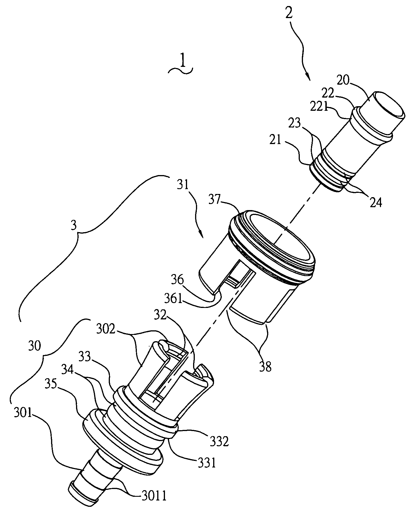
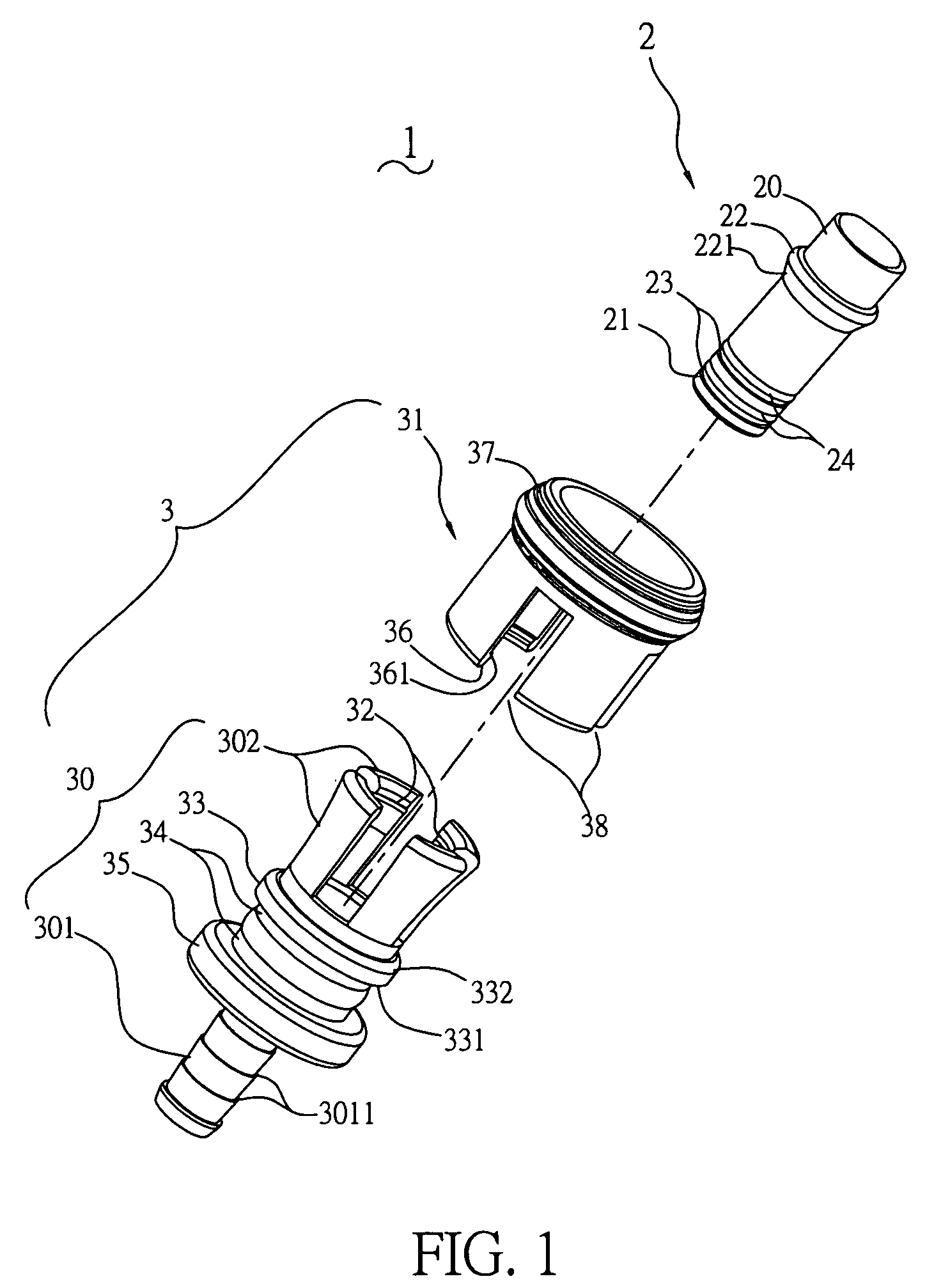
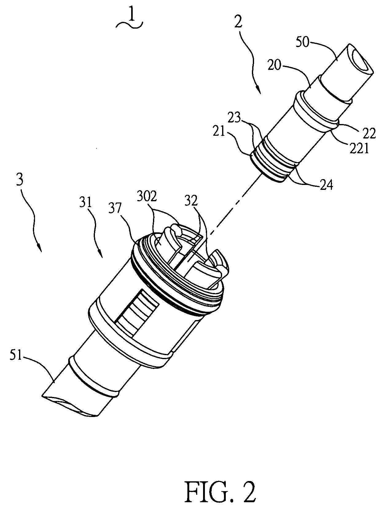
[0014]With reference to FIG. 1, an end fitting 1 in accordance with the present invention comprises a joining insert 2 and a pressing mechanism 3 assembled together. The joining insert 2 is a hollow tube, and includes a connecting end 20 and an inserting end 21 opposite to and communicating with each other. A first latch is formed on an outer surface of the joining insert 2 and in the vicinity of the connecting end 20. In one embodiment, the first latch comprises a projecting ring 22 unitarily formed on the joining insert 2. A guiding surface 221 is disposed on the projecting ring 22 and has lessened diameter toward the inserting end 21 for guiding assembly. Two recessed rings 23 are defined on the outer surface of the joining insert 2 and in the vicinity of the inserting end 21 for receiving leakproof rings 24, thereby preventing leakage of liquid in the joining insert 2 when assembled.

[0015]The pressing mechanism 3 includes a hollow retaining portion 30 and a pressing cover 31. A ...


PUM


Abstract

An end fitting has a joining insert and a pressing mechanism assembled together. The joining insert is hollow and includes a connecting end and an inserting end communicating with each other. The pressing mechanism includes a hollow retaining portion and a pressing cover. At least a holding tube extends integrally from an end of the retaining portion, and an arm portion with a plurality of branches extends from another end of the retaining portion and possesses appropriate flexibility. In practice, the arm portion of the retaining portion clamps the jointing insert, while the pressing cover restrains the arm portion. A first latch of the joining insert and a second latch of the retaining portion lock with a first embedding portion of the arm portion and a second embedding portion of the pressing cover, respectively. Hence, conduits are quickly fit to each other with eliminating need of tools.

Description

BACKGROUND OF THE INVENTION[0001]1. Field of the Invention[0002]The present invention relates to an end fitting, and particularly to an end fitting which joins at least two conduits tightly and quickly between ends of the conduits without need of auxiliary tools.[0003]2. Related Art[0004]Numerous conduits are employed in kitchens and bathrooms, and join each other with flexible conduits owing to limitation of operation conditions. Usually, a hard ring is retained on a tip of a flexible conduit, and connects a central conduit with a movable cap and a leakproof washer. In this way, the flexible conduit is directly fixed with an end of a conduit, as illustrated in U.S. Pat. Nos. 5,364,134 and 5,364,135.[0005]However, since tools are necessary to mount or dismount the flexible conduits in small space, assembly of the conduits is rather cumbersome. Especially, interconnection of an undersink faucet supply line is difficult.SUMMARY OF THE INVENTION[0006]Accordingly, an object of the prese...

Claims


Application Information

Patent Timeline
Patent Type & Authority Applications(United States)
IPC IPC(8): F16L21/06
CPCF16L37/0985E03C1/0403F16L37/133
Inventor LI-GUO, YAN
Owner GLOBE UNION INDAL
Why Eureka
Try Eureka