Method for detecting electrical ground faults

a ground fault and electrical technology, applied in the direction of short-circuit testing, emergency protective arrangements for limiting excess voltage/current, instruments, etc., can solve the problems of imposing a safety risk, no simple accurate method to check the integrity of an isolated ground conductor, and time-consuming methods

Inactive Publication Date: 2008-02-14
RABER MONTE B
View PDF4 Cites 34 Cited by
  • Summary
  • Abstract
  • Description
  • Claims
  • Application Information

AI Technical Summary

Problems solved by technology

At present there is no simple accurate method to check for the integrity of an isolated ground conductor in a powered branch circuit.
This method is time consuming, requires shutting off the power at the panel, imposes a safety risk, and requires a licensed electrician.
Several methods and instruments provide limited accuracy to detect such faults.
These methods suffer from lack of specificity, since they may erroneously indicate such a connection when conductor length to the distribution panel is short, or when the circuit is enclosed in non-metallic conduit.
These methods may involve applying the 120 volt line voltage to the ground circuit under test through a load, and so are not permitted in patient care areas of health care facilities.
The method is only practical before installing patients and equipment, involving disconnecting the system bit by bit, and measuring neutral-ground impedance as resistance downstream.
Low resistance other than hundreds of kilo-ohms indicated a fault, those found were largely improper neutral-ground connections, some were damaged insulation and the like.
The authors admit that locating faults as opposed to detecting faults, requires shutting down all or part of an electrical system, which may be impossible.
Direct checking at the panel is difficult and inconveni

Method used


Image

  • Method for detecting electrical ground faults
  • Method for detecting electrical ground faults
  • Method for detecting electrical ground faults

Examples


Embodiment Construction

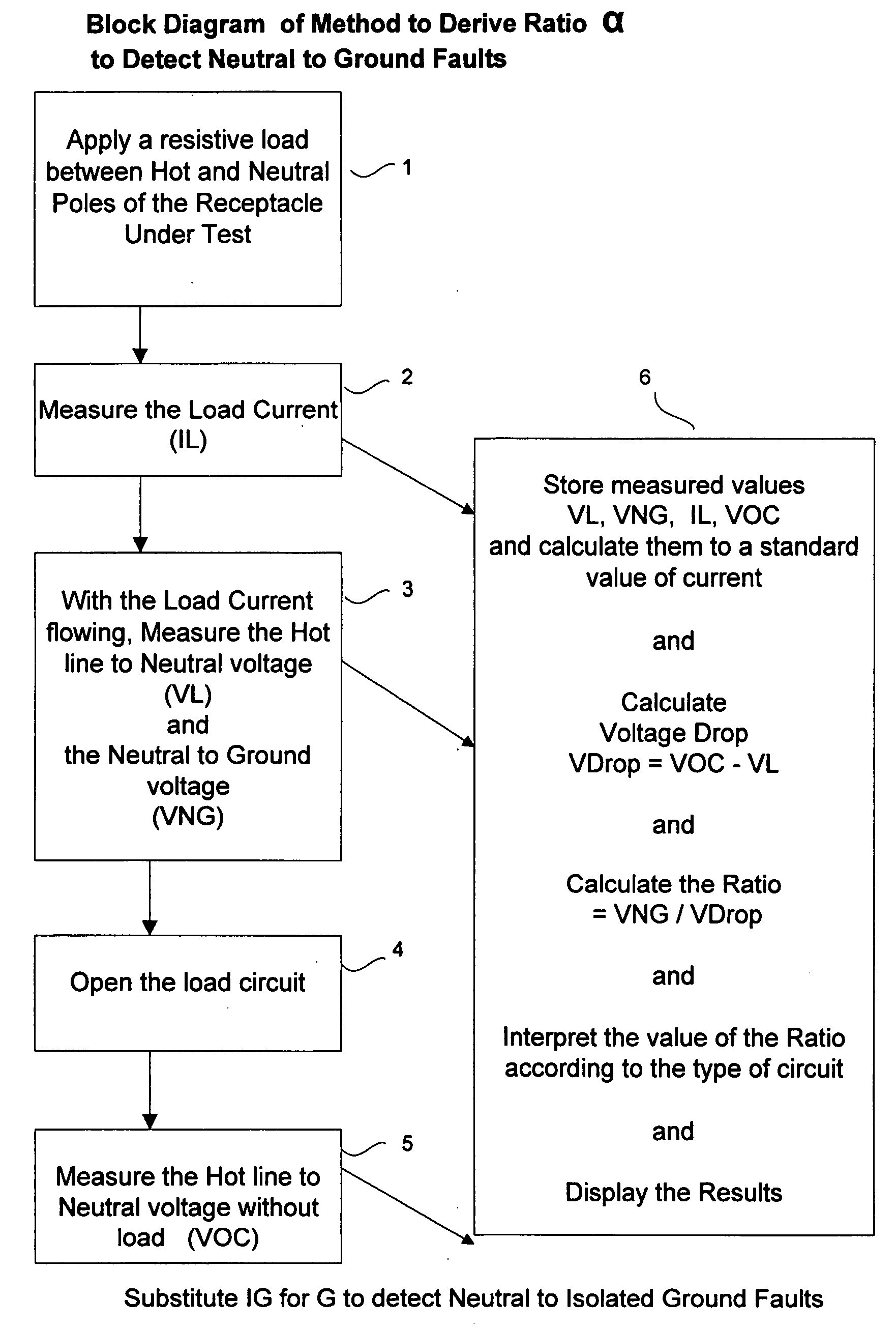
[0032]In a broadest aspect the invention is directed to a method of detecting faults in live circuits by comparing voltage drops across portions of the circuit, and expressing ratios of these voltage drops as indicative of faults. In general the voltage drop is a measure of the impedance of a portion of the circuit. Preferably the live circuits are alternating current, but would apply to equivalent direct current circuits. Generally the voltage drops are generated by passing electric currents between receptacle poles and measuring voltage drops caused by the electric currents.

[0033]Preferably the portions of the circuit are selected from the group consisting of neutral-ground loop, and hot-neutral loop, neutral-isolated ground loop, isolated ground-ground loop, and neutral conductor, ground conductor and isolated ground conductor. The portions of the circuit compared may be the hot-neutral loop and neutral-ground loop. The portions of the circuit compared may be the hot-neutral loop...


PUM


Abstract

A method of testing live AC circuits for neutral-ground, neutral-isolated ground, and isolated ground-ground faults, involves measuring impedances of circuit portions, including hot-neutral, neutral-ground, neutral-ground and isolated ground loops. In general either a test current generating a driving voltage is used, or in the case of hot-neutral, a load current generating a load voltage, and the voltage without current are use to measure voltage drop. These voltages are proportionate to the impedances of the circuits, which are expressed as ratios indicating the presence of faults. The method is reliable, despite much variation in circuit characteristics, including oversized neutral, shared neutral same phase, shared neutral opposed phase, supply line impedance, and high impedance grounds, it is easily able to detect faults across conductors and shared neutral loads.

Description

[0001]This application claims priority of U.S. provisional patent application No. 60 / 836,950, Method and tester for electrical ground faults, to Monte B. Raber, filed 11 Aug. 2006.[0002]This invention is directed to methods of detecting electrical ground faults and other interfering circuit conditions in live circuits. Generally ratios of voltage drops of circuit portions are measured, which are indicative of circuit fault status.[0003]As used in this application “ground” alone means safety or normal ground throughout this application. “Isolated ground” means isolated ground throughout this application, isolated ground is often called insulated ground. As used in this application “neutral conductor” refers to both an intact neutral conductor in the absence of faults, and as it appears to be in the presence of faults. “Receptacle” as used herein is interchangeable with “outlet.”BACKGROUND[0004]The basic problem is neutral-ground, neutral-isolated ground and isolated ground-ground fau...

Claims


Application Information

Patent Timeline
IPC IPC(8): G01R31/02
CPCG01R31/025G01R31/52
Inventor RABER, MONTE B.
Owner RABER MONTE B
Why Eureka
Try Eureka