
Fusion of far infrared and visible images in enhanced obstacle detection in automotive applications

a technology of visible and far infrared images, applied in image enhancement, scene recognition, instruments, etc., can solve the problems of low cost automotive qualified sensors sensitivity, loss of life and property, and inability to meet the needs of vehicles, and achieve the effect of improving the confidence of distance measured

Inactive Publication Date: 2008-02-14
MOBILEYE VISION TECH LTD
View PDF14 Cites 152 Cited by
  • Summary
  • Abstract
  • Description
  • Claims
  • Application Information

AI Technical Summary

Benefits of technology

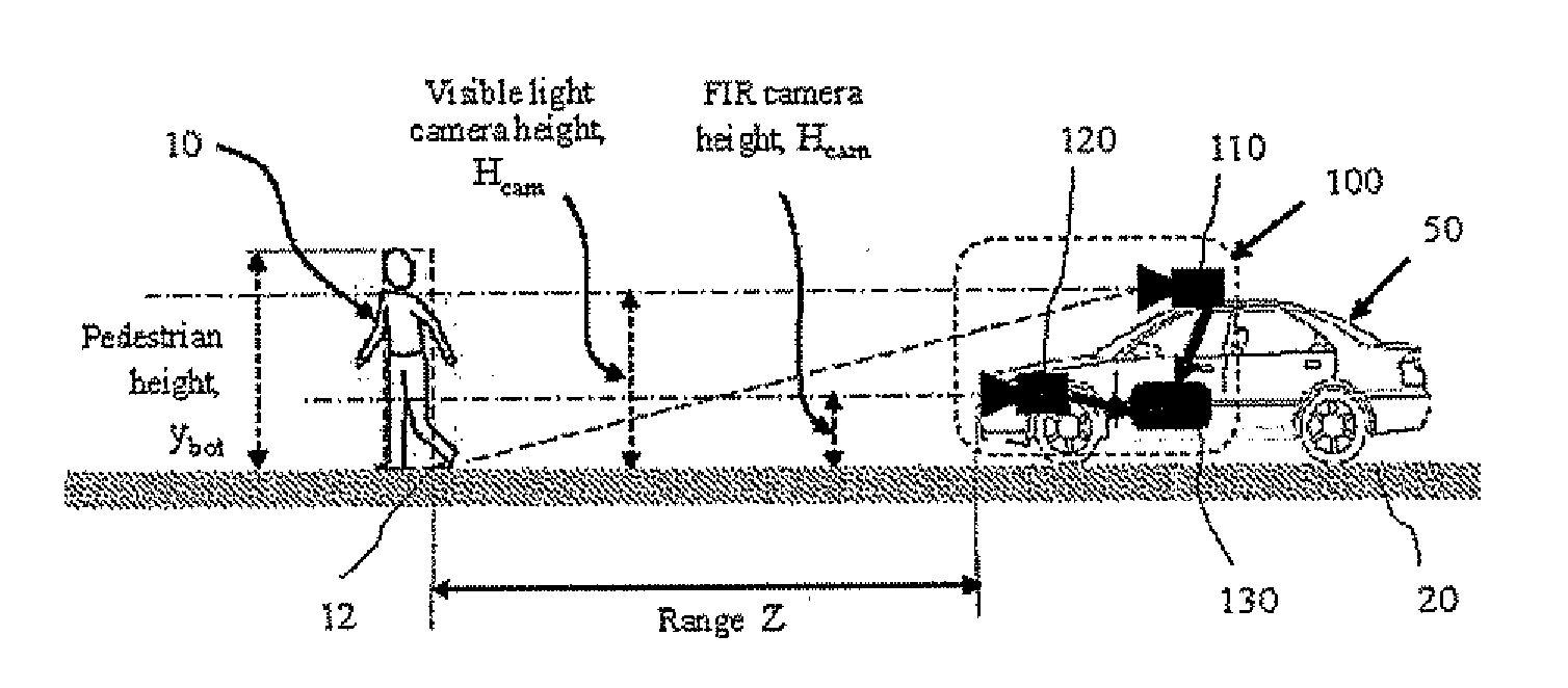
[0041]In a dark scene, at a distance over 25 meters, FIR images are used to detect warm objects such as pedestrians. At a distance of 25 meters and less, the distance from the vehicle front to the detected object illuminated by the vehicle headlights, is computed from one of the VIS images. The image location of the detected object in the VIS image is projected onto a location in one of the FIR images, the detected object is identified in the FIR image and the position of the detected object in the FIR image is aligned with the position of the detected object in the VIS image, the distance measured from the vehicle front to the object is used to refine by a stereo analysis of the simultaneously processed FIR and VIS images. The distance measured using the FIR image can also enhance the confidence of the distance measured using the VIS image.
[0044]In another method used by embodiments of the present invention, in a dark scene, at a distance over 10 meters, FIR images are used to detect warm objects such as pedestrians, vehicle tires, vehicle exhaust system and other heat emitting objects. The image location of the detected object in the FIR image is projected onto a location in one of the VIS images, the detected object is identified in the VIS image and the position of the detected object in the VIS image is aligned with the position of the detected object in the FIR image. The distance measured from the vehicle front to the object is used to refine by a stereo analysis of the simultaneously processed VIS and FIR images. The distance measured using the VIS image can also enhance the confidence of the distance measured using the FIR image. If no matching object is located in the VIS image, the camera gain and / or exposure the VIS camera / image can be adjusted until at least a portion of the object is located.

Problems solved by technology

Automotive accidents are a major cause of loss of life and property.
In the case of obstacle avoidance in automotive applications, to get an accurate distance estimates from a camera pair a “wide baseline” of at least 50 centimeters is needed, which would be ideal from a theoretical point of view, but is not practical since the resulting unit is very bulky.
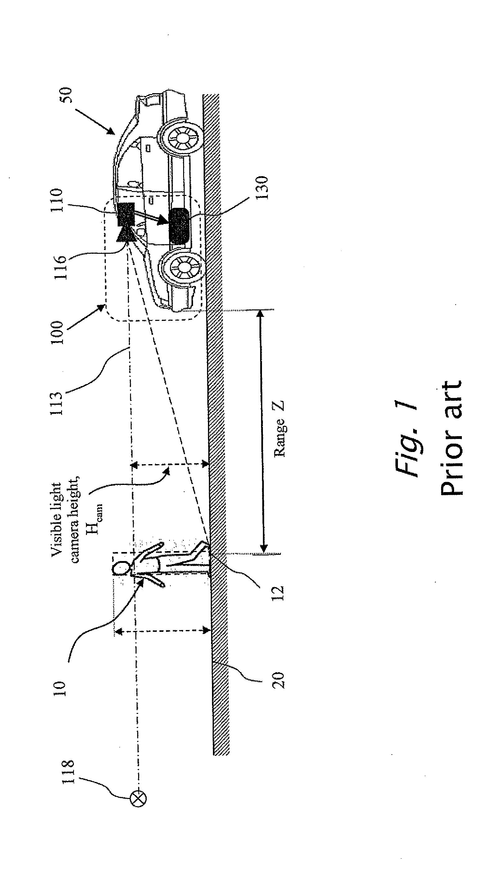
However, due to the limited sensitivity of low cost automotive qualified sensors, VIS camera 110 cannot detect pedestrians at night unless the pedestrians are in the area illuminated by the host vehicle 50 headlights.
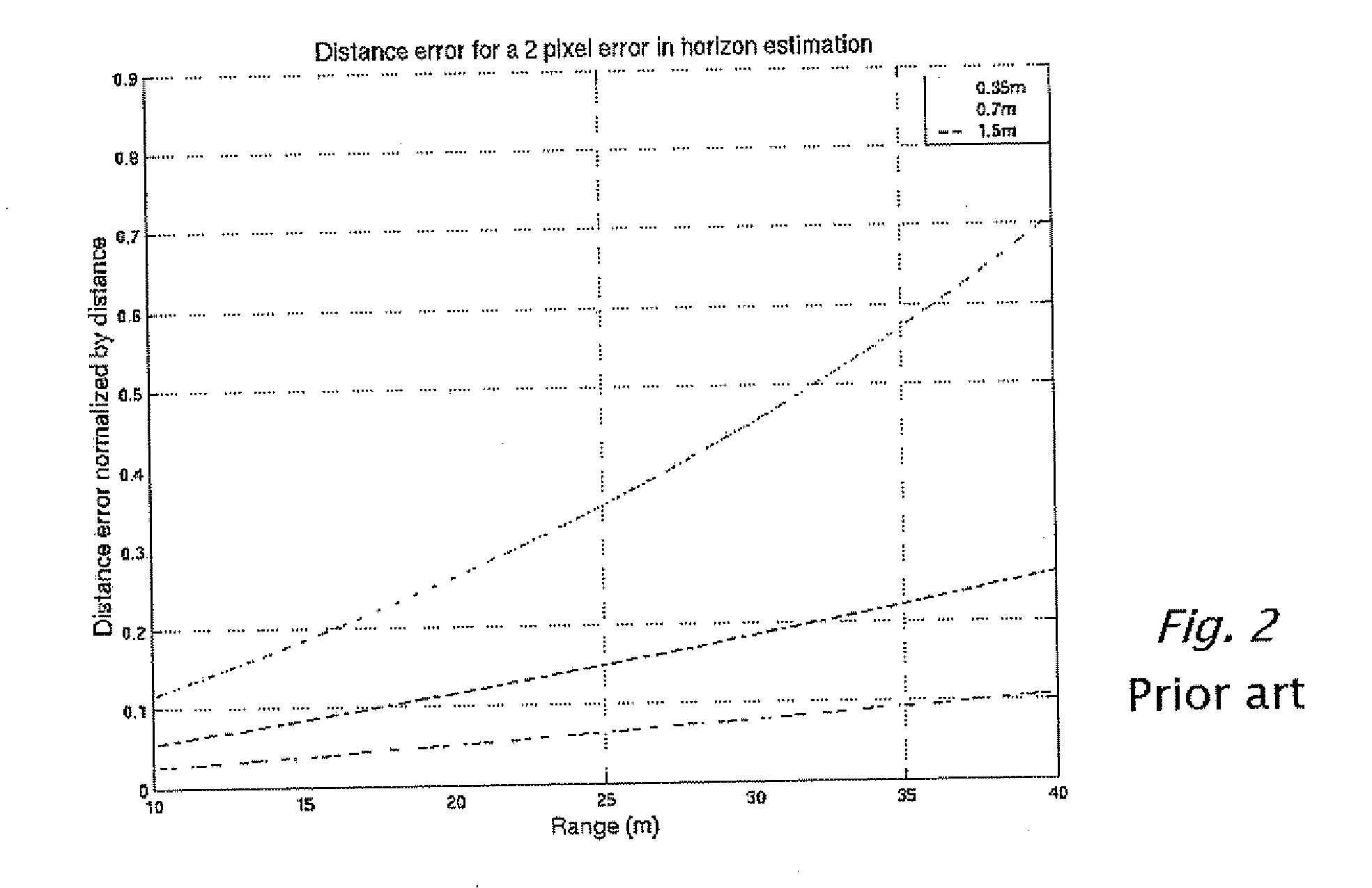
In conclusion, the errors in the range estimation, when using of road geometry constraints, can be very large for a camera height of 70 centimeters, and the value obtained is virtually useless.
With a FIR system, the target bottom 12 can still be determined accurately, however it is difficult to determine the exact horizon position, since road features such as lane markings are not visible.
Thus, in effect, the error in ybot can typically be 8-10 pixels, especially when driving on a bumpy road, or when the road curves up or down or when the host vehicle is accelerating and decelerating.
There are certain weather conditions, in which detecting pedestrians is more difficult.
Since the camera mounting is very low, range estimation using the ground plane constraint and triangulation is not possible.
FIR cameras are quite expensive, which makes a two FIR camera stereo system not a commercially viable option.
The problem is that to get accurate distance estimates from a camera pair, a “wide baseline” is needed, but a “wide baseline” results in a bulky unit which cannot be discretely installed.
A “wide baseline” of 50 centimeters or more would be ideal from a theoretical point of view, but is not practical.

Method used


Image

  • Fusion of far infrared and visible images in enhanced obstacle detection in automotive applications
  • Fusion of far infrared and visible images in enhanced obstacle detection in automotive applications
  • Fusion of far infrared and visible images in enhanced obstacle detection in automotive applications

Examples


second embodiment

[0120]FIG. 9 is flow diagram which illustrates a recursive algorithm 300 for refining distance measurements, in accordance with embodiments of the present invention. In the present invention, in step 320, an obstacle such as a vehicle is detected in the VIS image, acquired in step 312. A distance D to selected points of detected pedestrian 10 is computed in step 330 and then, a corresponding vehicle is then detected in the FIR image, acquired in step 310. In step 340, the rectangle representing pedestrian 10 in the VIS image is projected onto a location in the VIS image. In the next step 350, features between the detected targets in the two images are aligned and matched. During the daytime, the FIR image of the vehicle is searched for the bright spots corresponding to the target vehicle wheels and the exhaust pipe. In the visible light image, the tires appear as dark rectangles extending down at the two sides of the vehicle. The bumper is typically the lowest horizontal line in the...

third embodiment

[0124]FIG. 10 is flow diagram which illustrates a recursive algorithm 400 for tracking based on both FIR and VIS images acquired in respective step 410 and 412, in accordance with embodiments of the present invention. In the present invention, a pedestrian 10 is detected in step 420, in the FIR image, an accurate range l can be determined in step 430, and matched to a patch in the VIS image (as described above) in step 442. In step 280, the pedestrian 10 is tracked in each camera separately using standard SSD tracking techniques and the match is maintained. As the pedestrian 10 leaves FIR camera 120 FOV as determined in step 270, the tracking is maintained by VIS camera 110 in step 290. Since the absolute distance was determined while still in FIR camera 120 FOV, relative changes in the distance, which can be obtained from tracking, is sufficient to maintain accurate range estimates. The pedestrian 10 can then be tracked all the way till impact and appropriate active safety measures...

fourth embodiment

[0126]In the present invention, a vehicle target, whose distance has been roughly determined from VIS camera 110, is matched to a patch in the FIR image. The patch is then aligned. The aligned patch in the FIR image is then searched for the telltale features of a vehicle such as the hot tires and exhaust. If features are found the vehicle target is approved and appropriate action can be performed sooner, in step 262.


PUM


Abstract

A method in computerized system mounted on a vehicle including a cabin and an engine. The system including a visible (VIS) camera sensitive to visible light, the VIS camera mounted inside the cabin, wherein the VIS camera acquires consecutively in real time multiple image frames including VIS images of an object within a field of view of the VIS camera and in the environment of the vehicle. The system also including a FIR camera mounted on the vehicle in front of the engine, wherein the FIR camera acquires consecutively in real time multiple FIR image frames including FIR images of the object within a field of view of the FIR camera and in the environment of the vehicle. The FIR images and VIS images are processed simultaneously, thereby producing a detected object when the object is present in the environment.

Description

CROSS REFERENCE TO RELATED APPLICATIONS[0001]The present application claims the benefit under 35 USC 119(e) of U.S. provisional application 60 / 80,356 filed on May 31, 2006 by the present inventors, the disclosure of which is incorporated herein by reference.FIELD OF THE INVENTION[0002]The present invention relates to vehicle warning systems, and more particularly to vehicle warning systems based on a fusion of images acquired from a far infra red (FIR) camera and a visible (VIS) light camera.BACKGROUND OF THE INVENTION AND PRIOR ART[0003]Automotive accidents are a major cause of loss of life and property. It is estimated that over ten million people are involved in traffic accidents annually worldwide and that of this number, about tree million people are severely injured and about four hundred thousand are killed. A report “The Economic Cost of Motor Vehicle Crashes 1994” by Lawrence J. Blincoe published by the United States National Highway Traffic Safety Administration estimates ...

Claims


Application Information

Patent Timeline
Patent Type & Authority Applications(United States)
IPC IPC(8): B60Q1/00G06V10/143G06V10/147
CPCB60R1/00G06K9/00825B60R2300/106B60R2300/304B60R2300/8033B60R2300/804B60R2300/8053B60R2300/8093G06K9/00369G06K9/2018G06K9/209G06K9/6289G06T7/2033G06T2207/10048G06T2207/30261H04N7/18G06K9/00805B60R2300/105G08G1/167G06T7/246G06V40/103G06V20/58G06V20/584G06V10/143G06V10/147G06V10/803G06F18/251
Inventor STEIN, GIDEON S.SHASHUA, AMNONGDALYAHU, YORAMLIYATAN, HAREL
Owner MOBILEYE VISION TECH LTD
Learn More