Infrared light irradiating lamp for vehicle

a technology of infrared light and irradiating lamp, which is applied in the direction of point-like light source, lighting and heating apparatus, etc., can solve the problems of insufficient irradiation of infrared light in the direction of a side such as a pavement or a road shoulder, and difficulty in maintaining an excellent distance visibility, so as to prevent the increase of the incident angle of the light, the effect of reducing the transmittance and preventing the reduction of the transmi

Inactive Publication Date: 2008-02-14
KOITO MFG CO LTD
View PDF15 Cites 11 Cited by
  • Summary
  • Abstract
  • Description
  • Claims
  • Application Information

AI Technical Summary

Benefits of technology

[0018]In an infrared light irradiating lamp for a vehicle in accordance with one or more embodiments of the present invention, it is possible to prevent a transmittance from being reduced by the reflection of the infrared light transmitting filter.
[0019]More specifically, when the light reflected by the reflector passes through the infrared light transmitting filter, an incident angle of a light is increased, a reflectance is increased at a certain angle and a transmittance is reduced if the diffusing portion taking a concavo-convex shape is formed on an incident plane of the infrared light transmitting filter. In an infrared light irradiating lamp for a vehicle in accordance with one or more embodiments of the present invention, the diffusing portion taking the concavo-convex shape is formed on an emitting plane. Consequently, the incident angle of the light can be prevented from being increased, an increase in the reflectance can be suppressed and the transmittance (a filter efficiency) can be increased.

Problems solved by technology

Therefore, it is hard to maintain an excellent distant visibility.
On the other hand, when the light distribution pattern for the high beam has a priority, the infrared light is converged and is not diffused in a transverse direction in the irradiation of the infrared light so that the irradiation of the infrared light in a direction of a side such as a pavement or a shoulder of a road is insufficient.
For this reason, a usability is not always excellent.

Method used


Image

  • Infrared light irradiating lamp for vehicle
  • Infrared light irradiating lamp for vehicle
  • Infrared light irradiating lamp for vehicle

Examples


first embodiment

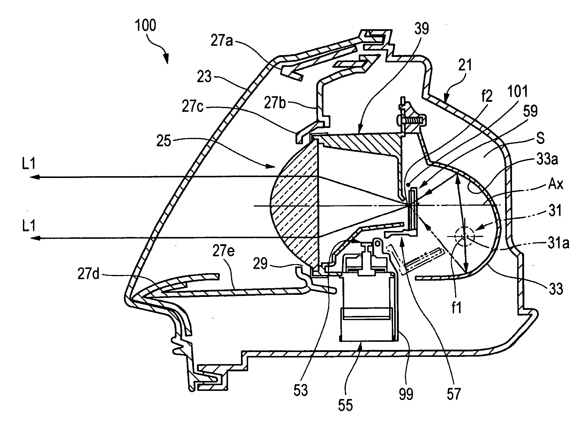
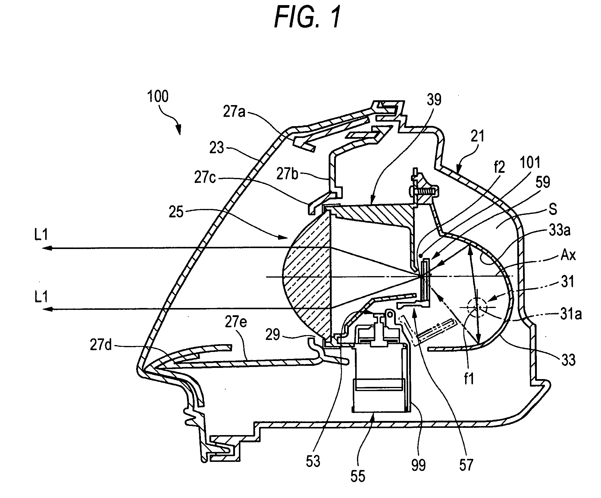
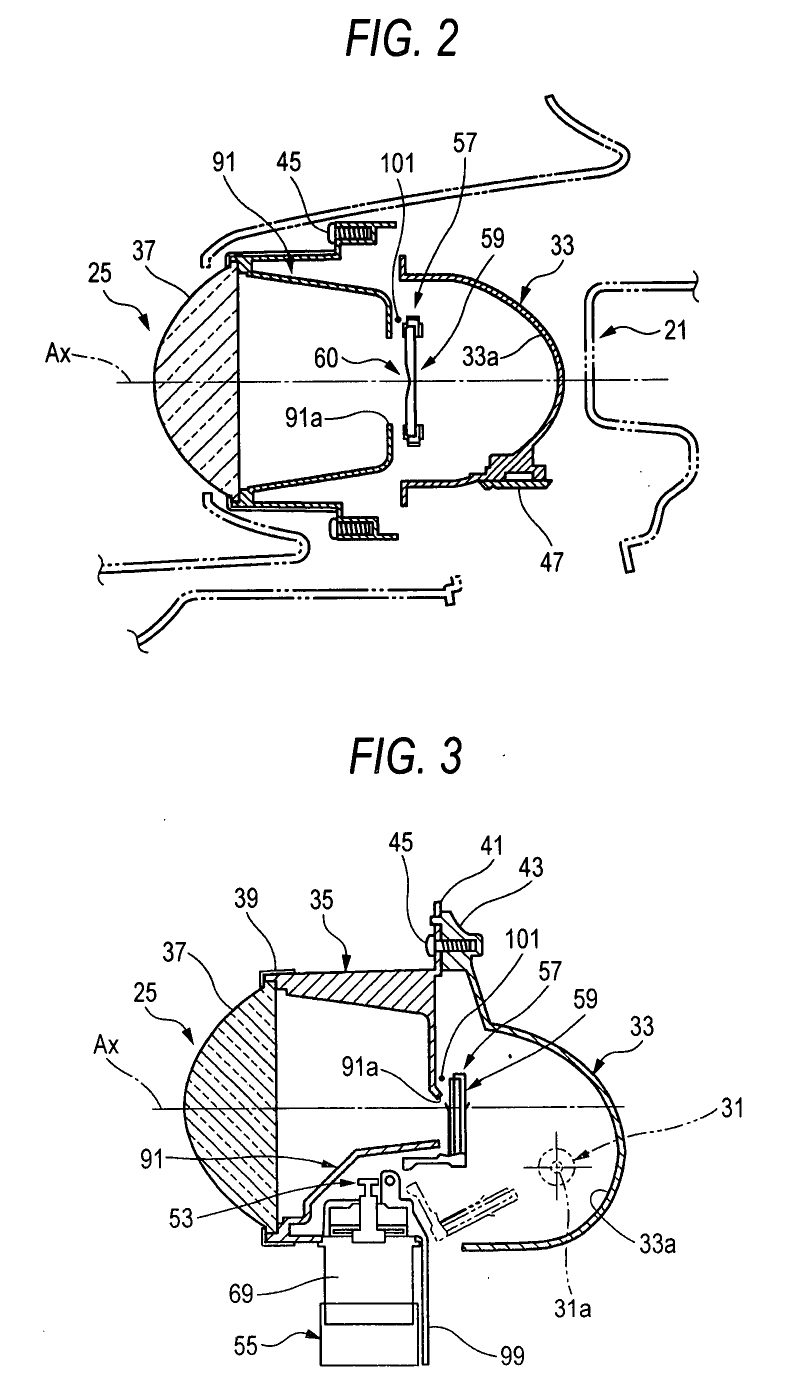
[0044]FIG. 1 is a vertical sectional view showing an infrared light irradiating lamp for a vehicle according to the invention, FIGS. 2 and 3 are horizontal and longitudinal sectional views of a light source unit illustrated in FIG. 1, and FIG. 4 is an exploded perspective view showing the light source unit illustrated in FIG. 1.

[0045]An infrared light irradiating lamp 100 for a vehicle according to the embodiment is used in a night forward visual field detecting system and is provided in a front portion of a vehicle to irradiate an infrared light onto a forward part of the vehicle, for example. The night forward visual field detecting system is constituted by the infrared light irradiating lamp 100 for a vehicle shown in FIG. 1, an infrared light compatible CCD camera (not shown) which is provided in an upper part in a vehicle compartment and serves to photograph a view of field in the forward part of the vehicle, for example, an image processing analyzing apparatus (not shown) for ...

second embodiment

[0091]Next, description will be given to an infrared light irradiating lamp for a vehicle according to the invention.

[0092]FIG. 9 is an enlarged perspective view showing an infrared light transmitting filter according to the second embodiment of the invention, and FIG. 10 is an explanatory view showing the function of the infrared light transmitting filter in which a diffusing portion taking a convex shape is formed. Since an infrared light irradiating lamp 200 for a vehicle according to the second embodiment has almost the same structure as that of the infrared light irradiating lamp 100 for a vehicle according to the first embodiment except for a structure of an infrared light transmitting filter 59A, common components have the same reference numerals and detailed description will be omitted.

[0093]In the infrared light irradiating lamp 200 for a vehicle according to the embodiment, the infrared light transmitting filter 59A is disposed in front of a rear side focal point f3 of a c...

third embodiment

[0096]Next, description will be given to an infrared light irradiating lamp for a vehicle according to the invention.

[0097]FIG. 11 is a perspective view showing an infrared light transmitting filter according to the third embodiment of the invention, and FIG. 12 is an explanatory view showing the function of the infrared light transmitting filter in which a light distribution regulating portion is formed. Since an infrared light irradiating lamp 300 for a vehicle according to the third embodiment has almost the same structure as that of the infrared light irradiating lamp 100 for a vehicle according to the first embodiment except for an infrared light transmitting filter 59B, common members have the same reference numerals and detailed description will be omitted.

[0098]In the infrared light irradiating lamp 300 for a vehicle according to the embodiment, the infrared light transmitting filter 59B is provided with a light distribution regulating portion 111 for converging a light tran...


PUM


Abstract

An infrared light irradiating lamp for a vehicle includes a projection lens disposed on an optical axis extending in a longitudinal direction of the vehicle; a light source bulb disposed behind a rear side focal point of the projection lens that includes a filament for emitting a light; a reflector for reflecting the light emitted from the light source bulb in a forward direction close to the optical axis; and an infrared light transmitting filter disposed between the reflector and the projection lens. The infrared light transmitting filter includes an infrared light transmitting film and a diffusing portion for diffusing a light transmitted from the reflector. The infrared light transmitting filter is movable between a transmitting position in which the infrared light transmitting film intercepts light reflected by the reflector and a retreating position in which infrared light transmitting film does not intercept the reflected light.

Description

[0001]This application claims foreign priority from Japanese Patent Application No. 2006-217482 filed on Aug. 9, 2006, the entire contents of which are hereby incorporated by reference.BACKGROUND OF INVENTION[0002]1. Field of the Invention[0003]The present invention relates to an infrared light irradiating lamp for a vehicle which can irradiate a light of a light source bulb having a filament as an infrared light by using a reflector, an infrared light transmitting filter and a projection lens.[0004]2. Background Art[0005]There is an infrared light irradiating lamp for a vehicle which is loaded onto a car and illuminates a forward part of a vehicle with an infrared light, and can process a photographed image to confirm an obstacle together with a CCD camera having a near-infrared sensitivity or less (for example, see Patent Document 1).[0006]As shown in FIG. 13, an infrared light irradiating lamp 1 for a vehicle of this type has such a structure that a light source bulb 9 to be a vi...

Claims


Application Information

Patent Timeline
Patent Type & Authority Applications(United States)
IPC IPC(8): B60Q1/04F21V9/00F21Y101/00
CPCF21V9/10F21S48/1136F21S41/13F21V9/40
Inventor KAGIYAMA, SHINJI
Owner KOITO MFG CO LTD
Why Eureka
Try Eureka