Optical Recording Medium Having a Control Layer

a control layer and recording medium technology, applied in the direction of data recording, instruments, disposition/mounting of heads, etc., can solve the problems of increasing the number of recording layers, increasing the difficulty of changeability and compatibility of recording media, and reducing the amount of light reflected from each recording layer with increasing total number of recording layers. achieve the effect of ensuring the changeability and compatibility of media, and accurate focus control of the light beam

Inactive Publication Date: 2008-02-14
PANASONIC CORP
View PDF16 Cites 6 Cited by
  • Summary
  • Abstract
  • Description
  • Claims
  • Application Information

AI Technical Summary

Benefits of technology

[0045] The optical pickup apparatus according to the present invention can carry out accurate focus control of the light beam in recording or reproduction.
[0046] This provides an optical pickup apparatus in which the changeability and compatibility of media is ensured, and in which a signal is recorded into or reproduced from a recording medium.

Problems solved by technology

Nevertheless, by superposing further semitransparent layers to make into multilayer structure, a problem occurs that the amount of light reflected from each recording layer decreases with increasing total number of the recording layers.
That is, there is the problem that the required accuracy in reflectivity rises with increasing total number of the recording layers.
Nevertheless, in the prior art recording media, each three-dimensional position is identified by a stage and / or a beam scanner, whereby when a medium is removed once, the same position is difficult to be specified again; this has caused a difficulty in the changeability and compatibility of recording media.

Method used


Image

  • Optical Recording Medium Having a Control Layer
  • Optical Recording Medium Having a Control Layer
  • Optical Recording Medium Having a Control Layer

Examples


embodiment 1

[0091] An optical recording medium, an optical pickup apparatus and a control apparatus for an optical recording medium according to Embodiment 1 of the invention are described below with reference to FIGS. 1-5.

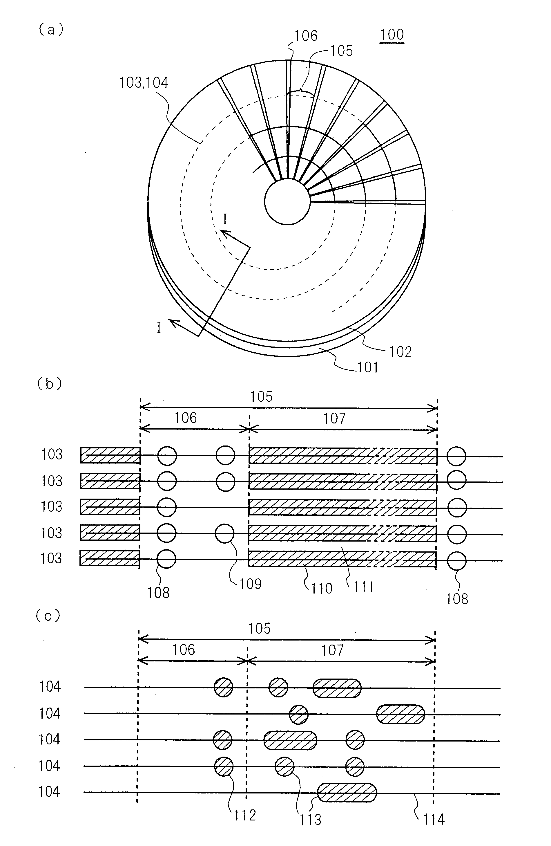
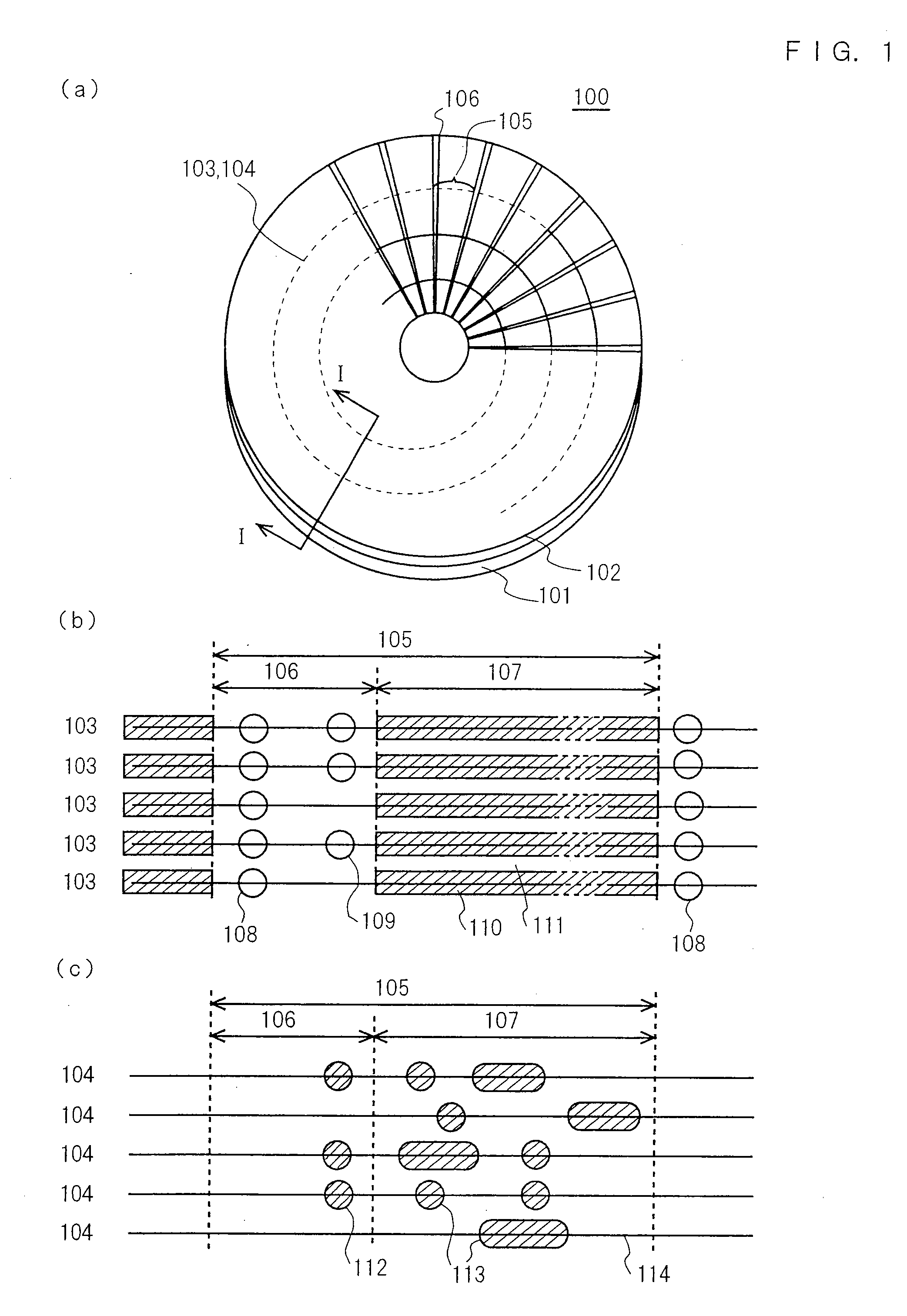
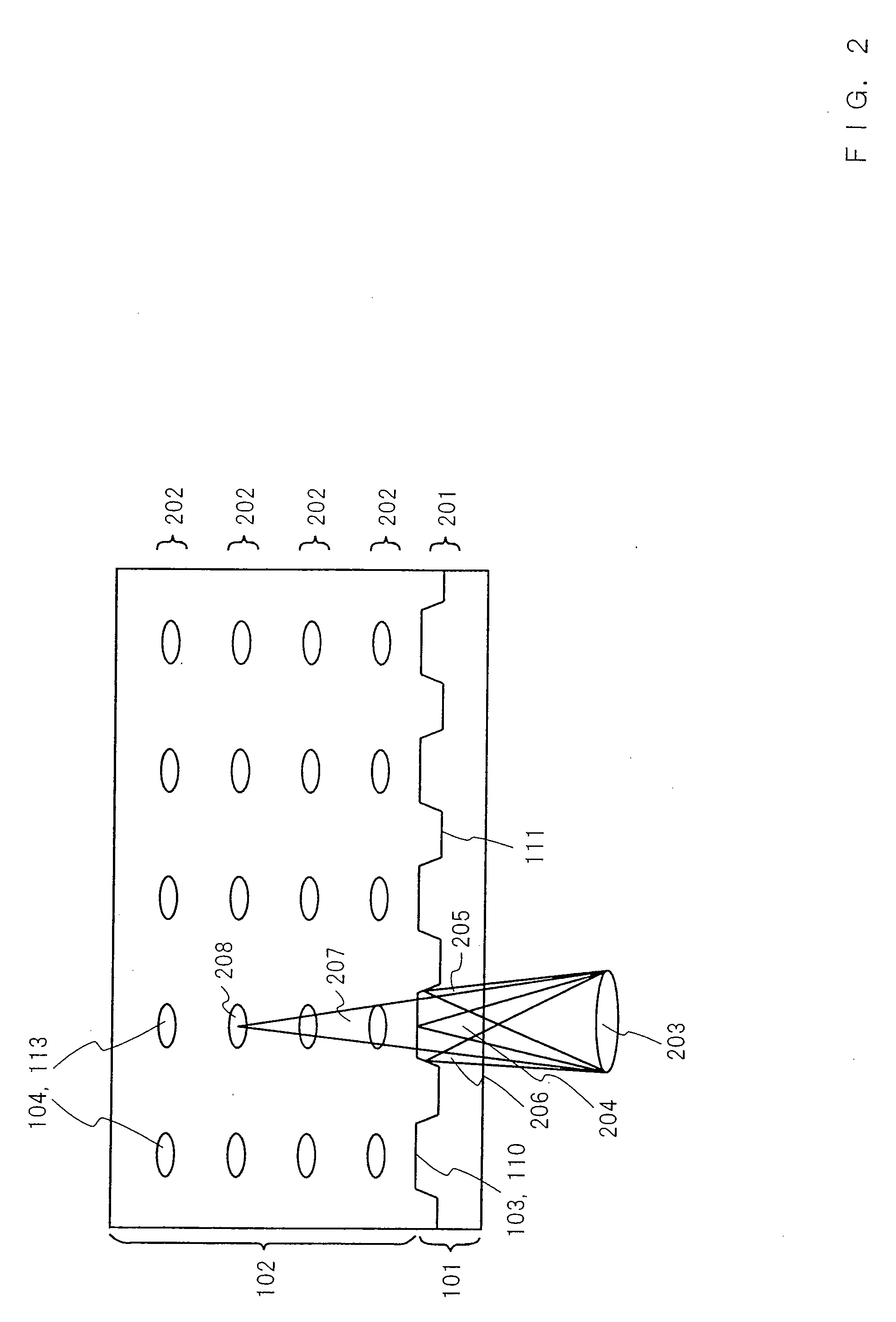
[0092] The structure of an optical recording medium according to Embodiment 1 is described below with reference to FIGS. 1 and 2. The optical recording medium according to Embodiment 1 is an optical disk for recording information in three dimensions in a photosensitive material.

[0093] In Embodiment 1, the photosensitive material is a photorefractive crystal (such as LiNbO3, BaTiO3 and LiIO3) having prominent nonlinearity with respect to light intensity. In place of this, the photosensitive material may be a resin containing photochromic molecules (such as spirobenzopyran) distributed therein, a photopolymer, a bichromate gelatin, a photographic emulsion film or the like.

[0094] When the photorefractive crystal is irradiated with strong light, the refractive index of the irr...

embodiment 2

[0181] An optical recording medium according to Embodiment 2 is described below with reference to FIG. 6. The optical recording medium according to Embodiment 2 is an optical disk for recording information in three dimensions in a photosensitive material.

[0182] The optical recording medium according to Embodiment 2 has the configuration shown in FIG. 1. (The only difference is that the control track 103 runs along the land 111.) The other points are the same as Embodiment 1, and hence the description of FIG. 1 is omitted.

[0183]FIG. 6 is a schematic cross sectional view of an optical recording medium according to Embodiment 2 of the invention, taken along line I-I of FIG. 1(a).

[0184] In the optical recording medium according to Embodiment 1, the control track 103 has been provided in the groove 110, while the recording tracks 104 have been provided in the positions superposed on the control track 103. In the optical recording medium according to Embodiment 2, a control track 103 i...

embodiment 3

[0187] An optical recording medium according to Embodiment 3 is described below with reference to FIG. 7. The optical recording medium according to Embodiment 3 is an optical disk for recording information in three dimensions in a photosensitive material.

[0188] The optical recording medium according to Embodiment 3 has the configuration shown in FIG. 1. (The only difference is that the control track 103 runs along both the groove 110 and the land 111.) The other points are the same as Embodiment 1, and hence the description of FIG. 1 is omitted.

[0189]FIG. 7 is a schematic cross sectional view of an optical recording medium according to Embodiment 3 of the invention, taken along line I-I of FIG. 1(a).

[0190] In the optical recording medium according to Embodiment 1, the control track 103 has been provided in the groove 110, while the recording tracks 104 have been provided in the positions superposed on the control track 103. In the optical recording medium according to Embodiment ...


PUM

PropertyMeasurementUnit
reflectivityaaaaaaaaaa
refractive indexaaaaaaaaaa
wavelengthaaaaaaaaaa

Abstract

An optical recording medium is disclosed. The optical recording medium includes an optical disk substrate. A control layer is formed on the optical disk substrate. The control layer includes a control track provided with a tracking control signal. A photosensitive material is formed on the control layer capable of forming a recording track as a result of a change in an optical property of the photosensitive material that is responsive to a specific light beam radiation. The optical property of all the recording tracks on a predetermined circumference of the optical disk substrate is entirely changed in advance.

Description

CROSS-REFERENCE TO RELATED APPLICATIONS [0001] This application is a divisional of co-pending U.S. application Ser. No. 10 / 145,156 filed May 14, 2002, the contents of which are incorporated herein by reference in their entirety.BACKGROUND OF THE INVENTION [0002] The present invention relates to an optical recording medium, an optical pickup apparatus and a control apparatus for an optical recording medium. [0003] With improvement in performance, recent computers frequently handle a large amount of information such as image data. This situation has caused demands for recording media and recording apparatuses having a large recording capacity. For the purpose of capacity enhancement in recording media, recording media having two or more recording layers have been developed and are commercially available. In the case of DVDs, the reflective coating of the incident-side recording layer is composed of a semitransparent film having a reflectivity of approximately 36%, while the second rec...

Claims


Application Information

Patent Timeline
Patent Type & Authority Applications(United States)
IPC IPC(8): G11B7/095G11B7/00G11B7/09G11B7/24038
CPCB82Y10/00G11B7/0901G11B2007/0013G11B7/0938G11B7/24038G11B7/0908
Inventor UENO, FUMIAKI
Owner PANASONIC CORP
Why Eureka
Try Eureka