
Diffraction element and optical pick-up apparatus having the same

Inactive Publication Date: 2006-06-08
SAMSUNG ELECTRONICS CO LTD
View PDF7 Cites 0 Cited by
  • Summary
  • Abstract
  • Description
  • Claims
  • Application Information

AI Technical Summary

Benefits of technology

[0011] Accordingly, an object of the present invention is to provide a diffraction element for an optical pick-up apparatus that allows more accurate focusing control, and an optical pick-up apparatus having the same.

Problems solved by technology

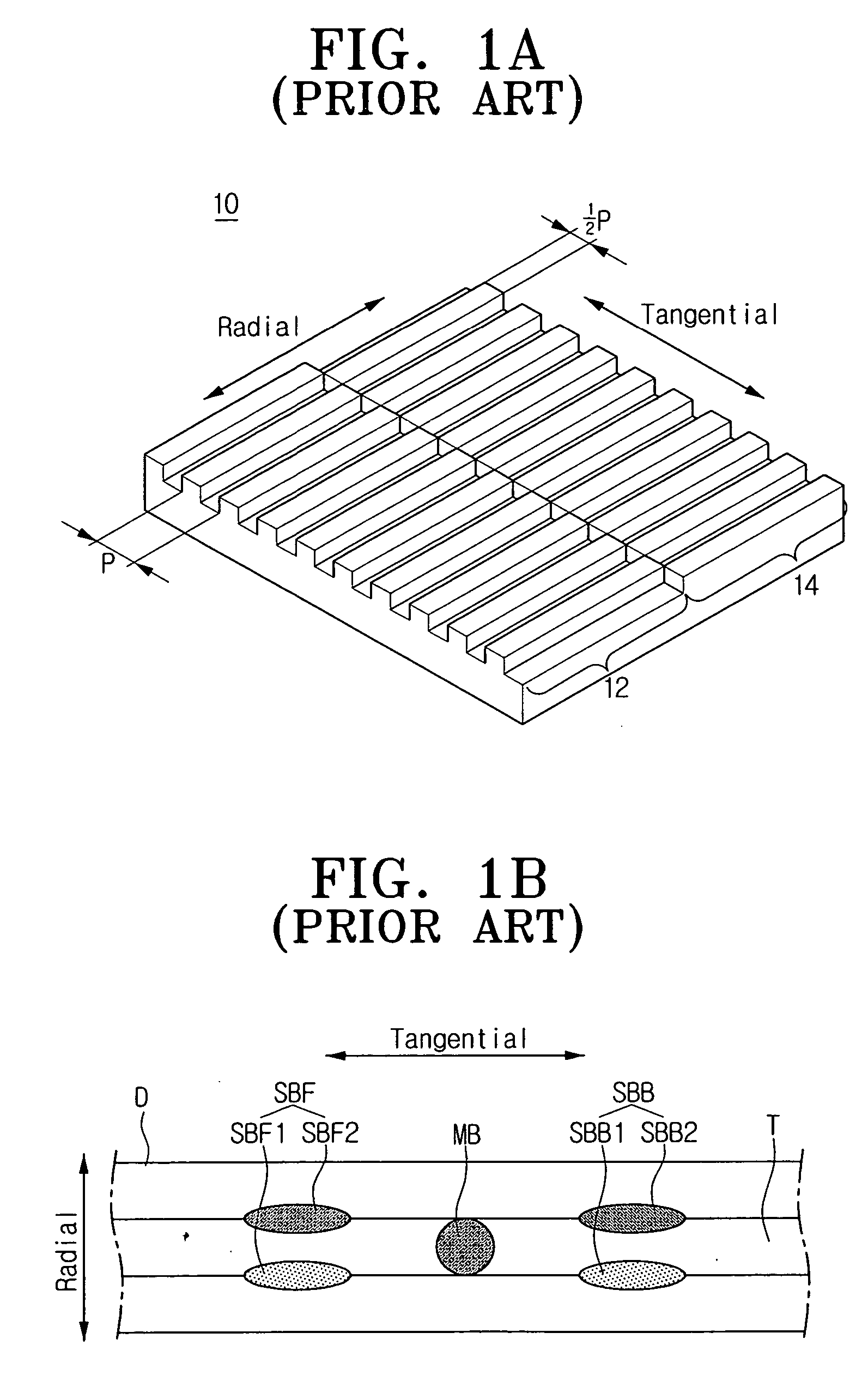
When the PP method is employed, a DC offset is produced in the TE signal due to objective lens shift and tilt caused as the tracking servo is performed, thereby causing an error in the TE signal.
However, it is not possible to employ such a DPP method for discs different from each other in specification of track pitch because illumination positions of sub-beams are varied in such discs.
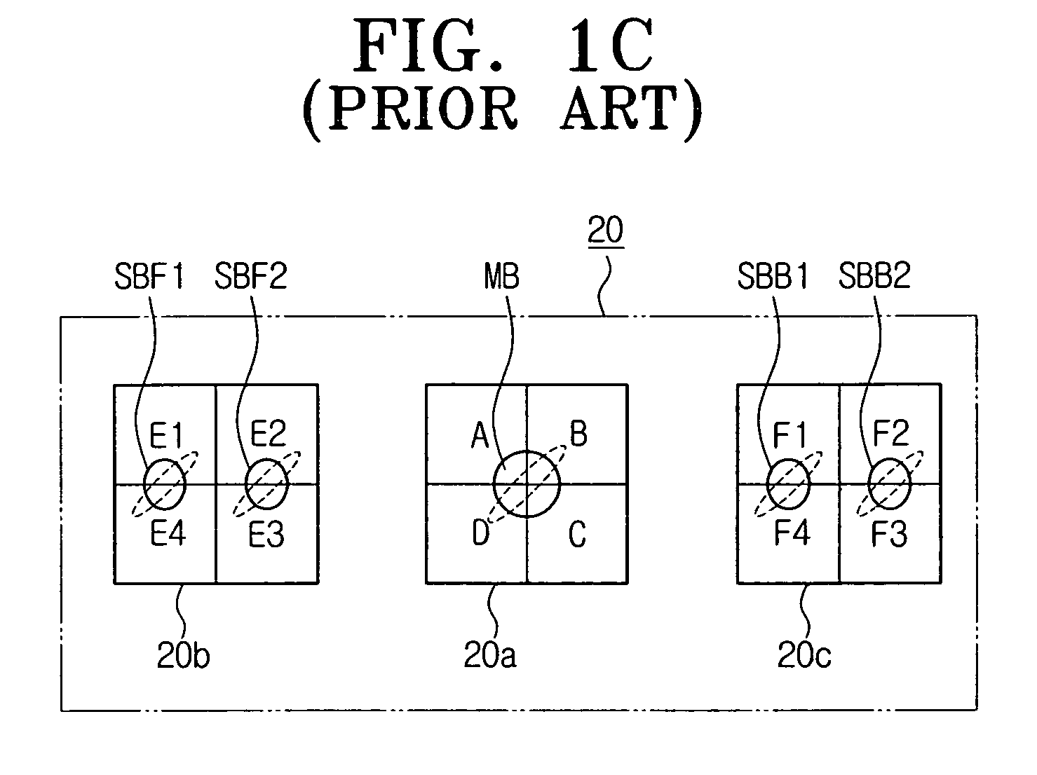
Therefore, an error can be caused in an FE signal determined through the differential astigmatism method, whereby not only the accuracy of focusing control but also the reliability of the optical pick-up apparatus may be deteriorated due to such an error.

Method used


Image

  • Diffraction element and optical pick-up apparatus having the same
  • Diffraction element and optical pick-up apparatus having the same
  • Diffraction element and optical pick-up apparatus having the same

Examples


Embodiment Construction

[0026] Hereinbelow, exemplary embodiments of the present invention are described in detail with reference to accompanying drawings.

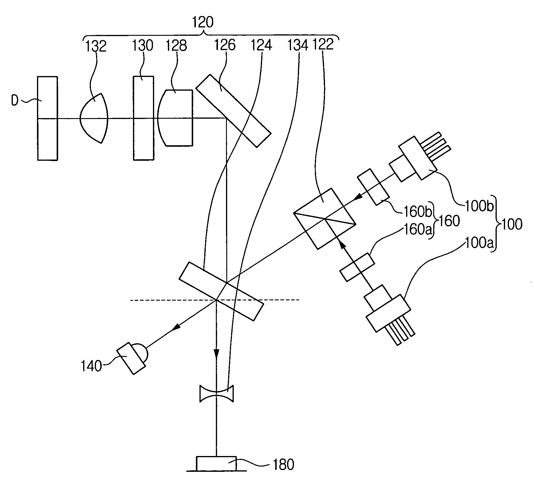
[0027] Referring to FIG. 2, an optical pick-up apparatus according to an exemplary embodiment of the present invention includes at least one light source 100, an optical system 120, a monitor optical detector 140, at least one diffraction element 160, and an optical detector 180. The monitor optical detector 140 may be implemented by an FPD (Front Photo Diode) and the optical detector 180 may be implemented by a PIDC (Photo Diode Integrated Circuit).

[0028] The at least one light source 100 includes a first light source 100a for a DVD and a second light source 100b for a CD. An LD (Laser Diode) with a wavelength is preferably employed in the light source 100. The first light source 100a records information on a DVD (Digital Versatile Disc) or reads information recorded on such a DVD, wherein the DVD has a track pitch (TP) (see FIG. 5) smaller than that ...


PUM


Abstract

A diffraction element for an optical pick-up apparatus is provided that enables more accurate focusing control. The diffraction element for an optical pick-up apparatus is divided into first and second regions, each being formed with a grid pattern in which grids are repeated with a predetermined pitch P. The grid pattern in at least one of the first and second regions is tilted by a predetermined angle with respect to a virtual line VL substantially perpendicular to a division line DL that divides the first and second regions.

Description

CROSS-REFERENCE TO RELATED APPLICATIONS [0001] This application claims the benefit under 35 U.S.C. § 119(a) of Korean Patent Application No. 2005-39404 filed May 11, 2005, in the Korean Intellectual Property Office, the entire disclosure of which is hereby incorporated by reference.BACKGROUND OF THE INVENTION [0002] 1. Field of the Invention [0003] The present invention relates to an optical pick-up apparatus. More particularly, the present invention relates to a diffraction element and an optical pick-up apparatus having the same. [0004] 2. Description of the Related Art [0005] An optical pick-up apparatus is employed in a CDP (Compact Disc Player), a DVDP (Digital Versatile Disc Player), a CD-ROM driver, or the like to perform recording and reproducing of information of a disc, which is an optical medium, in a contactless manner. When recording information, such an optical pick-up apparatus illuminates a laser beam onto a surface of a disc to form pits. When reproducing recorded i...

Claims


Application Information

Patent Timeline
IPC IPC(8): G11B7/135
CPCG11B7/0903G11B7/0909G11B7/1353G11B7/1381
Inventor KIM, BONG-GIPARK, SOO-HANYOO, JANG-HOON
Owner SAMSUNG ELECTRONICS CO LTD
Learn More