Control apparatus, control method, and storage medium

a control apparatus and control method technology, applied in the field of control apparatus, can solve the problems of deteriorating quality, unnecessary operation, and difficulty in and achieve the effect of high-speed and highly accurate focus control

Active Publication Date: 2021-05-13
CANON KK
View PDF0 Cites 3 Cited by
  • Summary
  • Abstract
  • Description
  • Claims
  • Application Information

AI Technical Summary

Benefits of technology

[0005]The present invention provides a control apparatus, a control method, and a storage medium, each of which can provide a high-speed and highly accurate focus control even when an imaging plane is tilted.

Problems solved by technology

However, the methods disclosed in JPs 2003-75716 and 2001-116980 provide a focus control using a contrast AF, and thus need a relatively long time.
In addition, they actually move the focus lens and the image sensor to calculate the tilt angle and the focus position, and thus the unnecessary operation deteriorates the quality.
However, the phase difference AF with the image sensor tilted may cause hunting and a high-speed and highly accurate focus control may become difficult.

Method used


Image

  • Control apparatus, control method, and storage medium
  • Control apparatus, control method, and storage medium
  • Control apparatus, control method, and storage medium

Examples


first embodiment

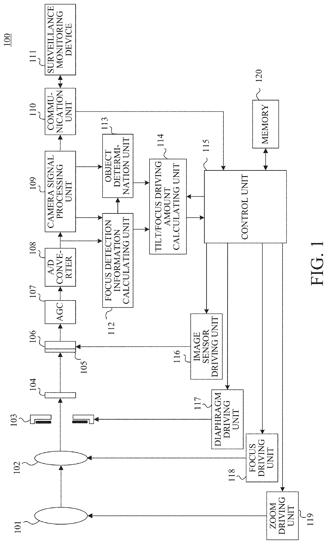
[0051]Referring now to FIG. 7, a description will he given of a control method (focus / tilt angle correction processing according to the tilt angle) according to a first embodiment. FIG. 7 is a flowchart of the control method according to this embodiment. Each step in FIG. 7 is mainly executed by the communication unit 110, the focus detection information calculating unit 112, the tilt / focus driving amount calculating unit 114, or the control unit 115.

[0052]First, in the step S701, the communication unit 110 sends a focus detection command to control unit 115. Next, in the step S702, the control unit 115 sends a focus detection command to the tilt / focus driving amount calculating unit 114 to start the focus detection. The defocus amount is calculated for two focus detection positions in the steps S702 to S707, but the focus detection calculation will be described at one focus detection position to simplify the description.

[0053]Next, in the step S703, the focus detection information ...

second embodiment

[0069]Referring now to FIG. 12, a description will be given of a control method (focusing and tilt angle correction processing according to the tilt angle) according to a second embodiment. FIG. 12 is a flowchart of the control method according to this embodiment. Each step in FIG. 12 is mainly executed by the communication unit 110, the focus detection information calculating unit 112, the tilt / focus driving amount calculating unit 114, or the control unit 115.

[0070]This embodiment is different from the first embodiment (FIG. 7) in that the focus detection method is changed based on the correction amount (the steps S1205 and S1212 are inserted into FIG. 12). Other configurations and methods in this embodiment are the same as those in the first embodiment, and therefore a description thereof will be omitted.

[0071]In the step S1204, the focus detection information calculating unit 112 determines a correction amount (shading correction coefficient) during the shading correction. Next,...


PUM


Abstract

A control apparatus includes an acquisition unit configured to acquire optical information, a tilt control unit configured to tilt an image sensor relative to a plane orthogonal to an optical axis of an imaging optical system, and a calculation unit configured to calculate an image shift amount by a phase difference detection method based on a signal from the image sensor and to calculate a defocus amount based on the image shift amount and a conversion coefficient. The calculation unit changes at least one of a correction amount of the signal and the conversion coefficient based on the optical information and a tilt angle that is an angle formed by the image sensor and the plane.

Description

BACKGROUND OF THE INVENTIONField of the Invention[0001]The present invention relates to a control apparatus that provides a focus control and a tilt control.Description of the Related Art[0002]The technology called the Scheimpflug principle has conventionally been known which extends a depth of field by relatively tilting a lens and an image sensor. Japanese Patent Laid-Open No. (“JP”) 2003-75716 discloses a method for executing, for each object, processing that controls a focus position so as to maximize a contrast evaluation value, and for determining the focus position and a tilt control amount so as to focus on a plurality of objects, JP 2001-116980 discloses a method for driving the focus position from one end to the other end and for storing a focus position so as to maximize a contrast evaluation value for each object.[0003]However, the methods disclosed in JPs 2003-75716 and 2001-116980 provide a focus control using a contrast AF, and thus need a relatively long time. In add...

Claims


Application Information

Patent Timeline
Patent Type & Authority Applications(United States)
IPC IPC(8): H04N5/232
CPCH04N5/23299H04N5/23296H04N5/23212H04N23/67H04N25/11H04N23/84G02B7/38G02B7/34G02B7/36G02B7/09G02B7/105G02B7/102H04N23/695H04N23/69
Inventor KIMURA, HIROAKI
Owner CANON KK
Why Eureka
Try Eureka