Canal lock system

a canal lock and lock technology, applied in dry docks, climate change adaptation, ship lifting devices, etc., can solve the problems of water spillage into the ocean, inability to prevent contamination or species exchange, and high construction and maintenance costs of water pumps

Inactive Publication Date: 2008-02-14
ALLONCA MANUEL G
View PDF16 Cites 11 Cited by
  • Summary
  • Abstract
  • Description
  • Claims
  • Application Information

AI Technical Summary

Benefits of technology

[0007]According to a first broad aspect of the present invention there is provided a canal lock system comprising: at least one canal lock having a bottom and a first water level; at least one reservoir for holding recirculated water connected to the bottom of the at least one canal lock; and at least one air pump connected to the at least one reservoir for pressurizing the at least one reservoir with air to force the water into the at least one lock to thereby change the first water level in the at least one canal lock to a higher second water level, wherein the at least one reservoir maintains a constant volume and wherein the at least one reservoir is depressurized to receive the water from the at least one lock to thereby change the second water level to a lower third water level.
[0008]According to a second broad aspect of the present invention there is provided a canal lock system comprising: at least one canal lock; at least one reservoir that holds recirculated water; means for pressurizi

Problems solved by technology

As a result, each time a ship passes through the canal locks water is spilled from the source and into the ocean.
In addition, to the waste of water, such conventional systems also do not prevent contamina

Method used


Image

  • Canal lock system
  • Canal lock system
  • Canal lock system

Examples


Embodiment Construction

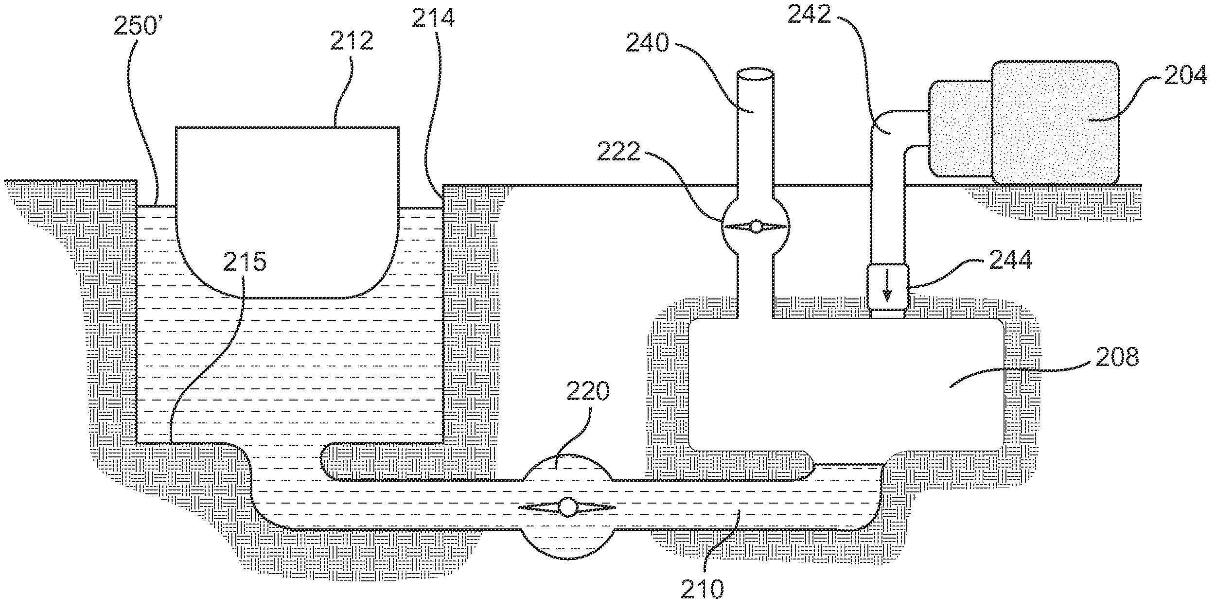
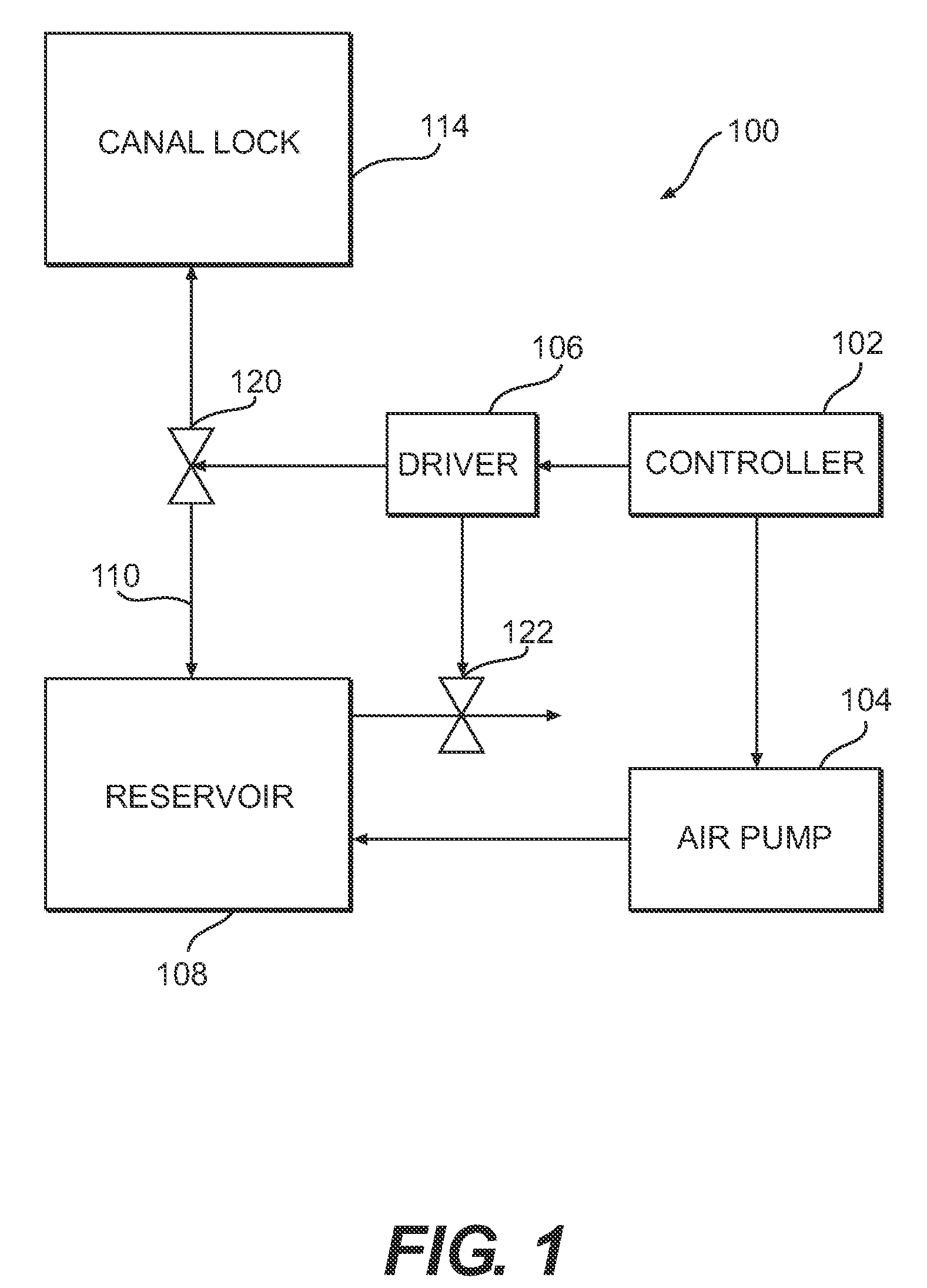
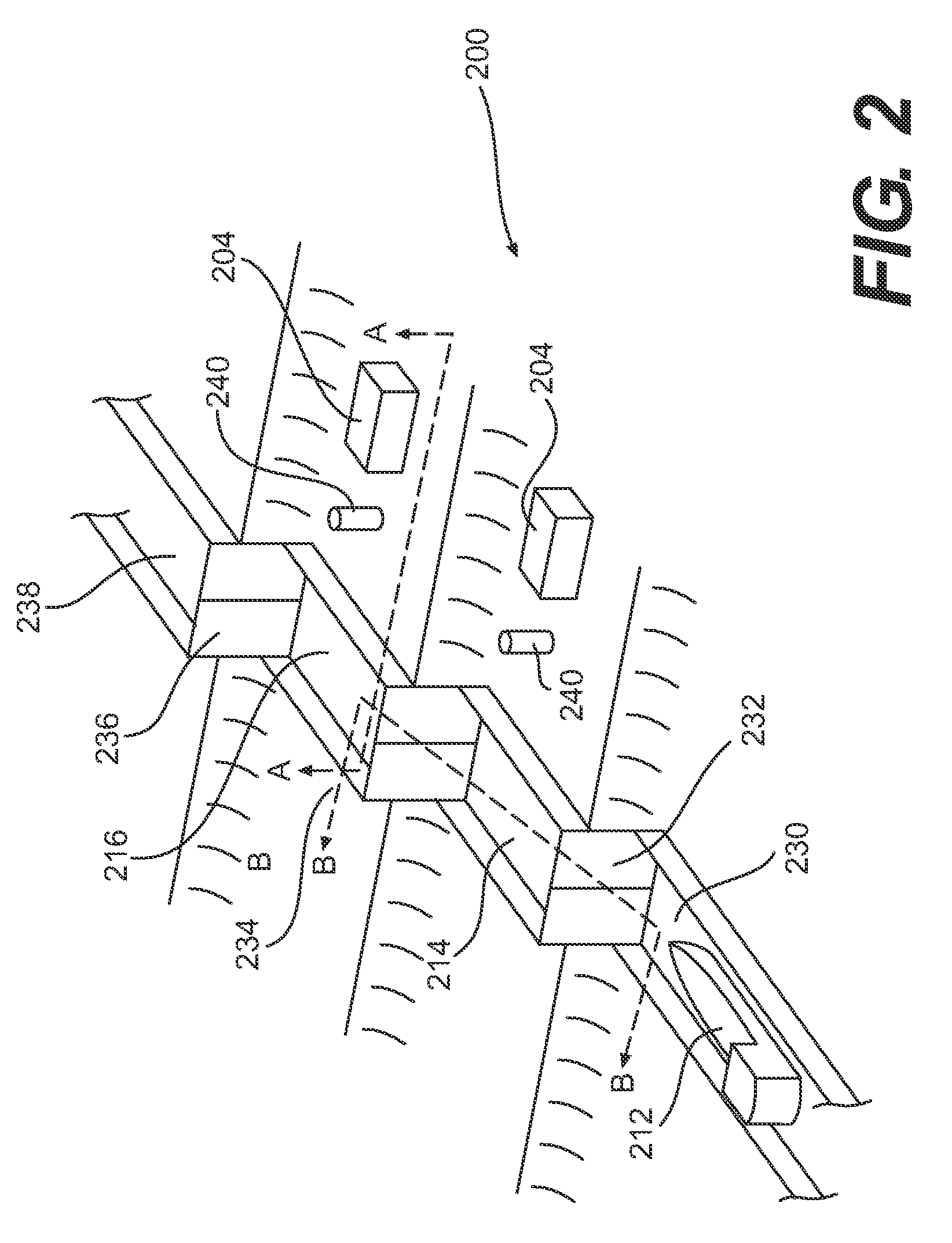
[0023]The embodiments of the present invention provide a canal lock system that raises and lowers the water in at least one canal lock having a bottom using air pressure. The air pressure may be supplied by at least one air pump. The air pump pressurizes the at least one reservoir with air to force water out of at least one reservoir, where each reservoir is connected to the bottom of each canal lock to thereby raise the water level in each canal lock. Air pressure is released to depressurize the at least one reservoir to receive water from each canal lock to thereby lower the water level in each canal lock. When the water level in each canal lock is raised or lowered, a ship in the canal lock is also raised or lowered. Such embodiments provide a canal lock system that recirculates the water from the at least one reservoir to each canal lock. By recirculating the water from the at least one reservoir, the amount of water wasted is minimized as well as reducing contamination and spec...


PUM


Abstract

A canal lock system for recirculating water between a reservoir and canal lock that uses air pressure to change the water level in the canal lock. The canal lock system comprises at least one canal lock, at least one reservoir for holding recirculated water connected to the bottom of the at least one canal lock, and at least one air pump connected to the at least one reservoir for pressurizing the at least one reservoir with air to force the water into the at least one lock to thereby change a first water level in the at least one canal lock to a higher second water level, wherein the at least one reservoir maintains a constant volume and wherein the at least one reservoir is depressurized to thereby change the second water level to a lower third water level.

Description

CROSS-REFERENCE TO RELATED APPLICATIONS[0001]This application makes reference to and claims the priority date of the following co-pending U.S. Provisional Patent Application: U.S. Provisional Patent Application No. 60 / 822,309, entitled “Canal Lock System,” filed Aug. 14, 2006. The entire disclosure and contents of the above application is hereby incorporated by reference.BACKGROUND[0002]1. Field of the Invention[0003]The present invention generally relates to a canal lock system for raising or lowering a ship in a canal lock from one water level to another water level by pressurizing a reservoir holding recirculating water connected to the canal lock with air to raise the water level in the canal lock, and depressurizing the reservoir to lower the water level in the canal lock. The present invention also generally relates to a method for operating the canal lock system.[0004]2. Related Art[0005]Canals are widely used to raise and lower ships from one level to another level, thereby ...

Claims


Application Information

Patent Timeline
IPC IPC(8): E02C1/06
CPCE02C1/06Y02A10/30
Inventor ALLONCA, MANUEL G.
Owner ALLONCA MANUEL G
Why Eureka
Try Eureka