
Ventilation system

Inactive Publication Date: 2008-02-14
INNOSOURCE
View PDF14 Cites 6 Cited by
  • Summary
  • Abstract
  • Description
  • Claims
  • Application Information

AI Technical Summary

Benefits of technology

[0010] Because only very small amounts of air are moved in the building it is no longer necessary to take special measures to restrict the heat loss as far as possible. Consequently, it is not necessary to use complex constructions for heat recovery. More particularly, with the present invention it is possible to dispense with a heat exchanger in the air extractor that warms up air that has just been drawn in from outside, immediately or later. As a result it is possible to set up a ventilation system in a completely different way, that is to say with a central air extractor, the position of which is completely independent of the air blower. It is possible accurately to determine the amount of air introduced / extracted only by measurement. Such a measurement can be implemented using any construction known in the state of the art, for example using air speed meters and the like. It is also possible to determine the resistance of the fan motor in the air in the manner described below and to draw conclusions with regard to the flow rate on the basis of this determination.
[0015] By means of this system, which enables very accurate adjustment to the various actually prevailing conditions, it is possible to ventilate with a relatively small amount of air, as a result of which the heat losses are negligible. Of course, it is always possible to use heat exchangers in the extractor.
[0018] In order to optimise the control in the various rooms, according to an advantageous embodiment there are sensors in the various rooms. These measure the conditions prevailing therein. An important factor is the percentage of CO2. This is a measure for the number of people and the activity of those people who are in a specific room. It is easily possible to measure this percentage and on the basis thereof to admit more or less air from the outside. It is also possible to determine other parameters in certain rooms, such as the humidity in a kitchen. Moreover, a signal can be given manually to the control device if, for example, additional build-up of moisture is to be expected in the kitchen during cooking. For this purpose there can be a switch in the vicinity of, for example, the extractor. Another important parameter is, as indicated above, the wind speed acting on the building. By measuring the air speed at the location of the blower, the flow rate can be corrected, that is to say the blower can start to run at a higher or lower rate. If the wind is blowing onto the blower, the energy supplied will become less and if the wind is blowing away from this a higher speed of revolution or more work on the part of the fan concerned will be required. This control by means of sensors can be independent of or combined with the control based on ways of life described above.

Problems solved by technology

However, this requires that the central extractor has an appreciable power and extraction is also accompanied by the loss of an appreciable proportion of the heat.
The latter can be compensated by installing a heat exchanger in the central extractor, but this is associated with appreciable technical and practical problems.

Method used


Image

  • Ventilation system
  • Ventilation system

Examples


Embodiment Construction

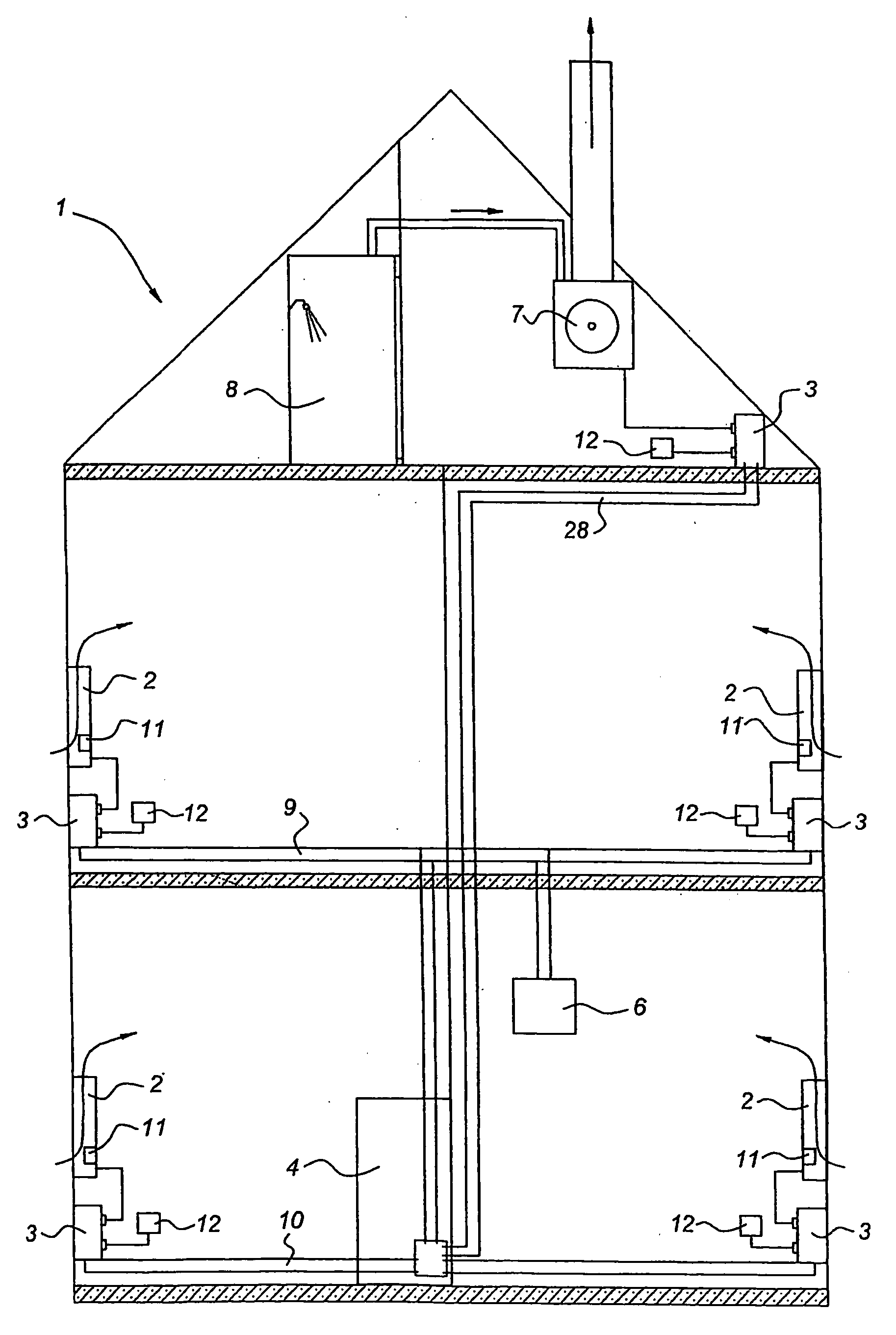
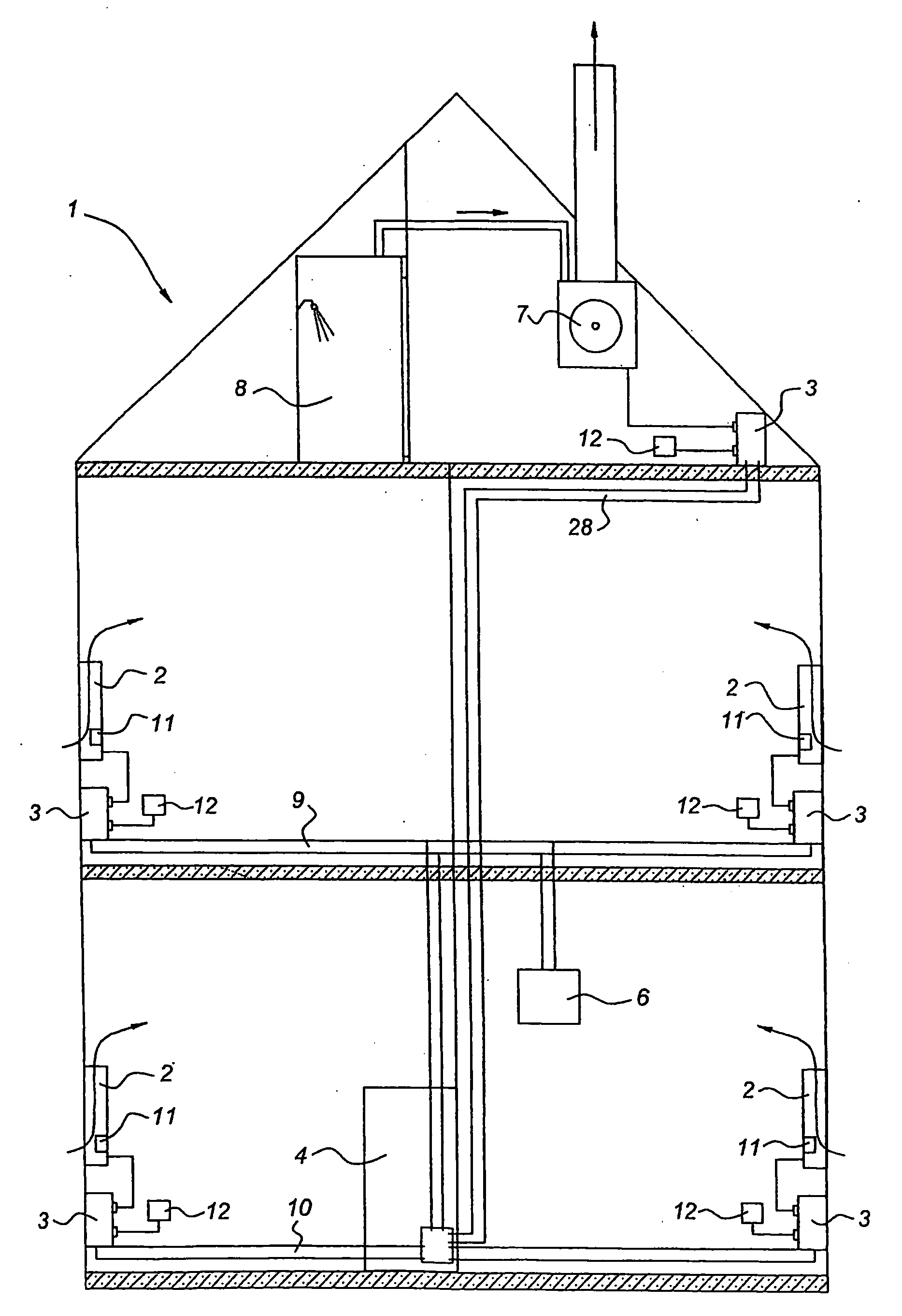
[0027] In FIG. 1 a building is indicated by 1. The blowers are indicated diagrammatically by 2. Various sockets are indicated by 3. The attic floor of the building is provided with a mains network 28, the first floor with mains network 9 and the ground floor with mains network 10. These mains network are on different phases and come together in the meter cupboard 4. An extractor 7 has been installed in the top of the building. This provides extraction for, inter alia, a shower room 8. Via the various chinks between doors and the like, extraction from the shower room 8 results in a reduced pressure in the building. However, this is negated by the action of the blowers 2. Control of the blowers 2 takes place with the aid of a control unit or central controller 6. This is likewise connected to the mains network 9. This connection of the controller 6 and of the blowers 2 to the mains network is the only connection. With the aid of the multiplexing technique it is possible to control the...


PUM


Abstract

A ventilation system for a building has blowers installed in a number of rooms for occupation, for blowing fresh outside air directly into said rooms. There is a central extractor and with the aid of a control device, the amount of air blown in is controlled for each of the rooms as required. Connection of the various components described above is via the mains network.

Description

CROSS-REFERENCE TO RELATED APPLICATION [0001] This application is a continuation of co-pending application Ser. No. 10 / 544,078, filed Jul. 29, 2005, entitled VENTILATION SYSTEM, which is incorporated herein by reference.BACKGROUND OF THE INVENTION [0002] (1) Field of the Invention [0003] The present invention relates to a ventilation system for a building. Numerous ventilation systems are known in the state of the art. A first system is that in which air is extracted from the various rooms by a central unit and, optionally with the addition of further air originating from the environment, is blown back into the rooms. Such a system can be used only for somewhat larger buildings and demands appreciable structural modifications. [0004] (2) Description of the Related Art [0005] A further system consists in the use of a single extractor in which a fan has been fitted. Ventilation openings are made in the various rooms of the building. If these ventilation openings are made relatively la...

Claims


Application Information

Patent Timeline
IPC IPC(8): F24F11/02F24F7/08F24F11/00
CPCF24F7/08F24F11/0079F24F2011/0027F24F2011/0038F24F2011/0068E05F15/71Y02B30/78F24F11/0001F24F2007/001F24F2011/0002Y02B30/746F24F2110/72F24F2110/30F24F11/56F24F11/77Y02B30/70
Inventor VROEGE, NORBERT PETER
Owner INNOSOURCE
Learn More