
Personal assistive breathing apparatus

Inactive Publication Date: 2008-02-21
GO2
View PDF8 Cites 10 Cited by
  • Summary
  • Abstract
  • Description
  • Claims
  • Application Information

AI Technical Summary

Benefits of technology

[0016]Another aspect of the present invention involves the use of a secure triggering or actuation mechanism that enables operation with a single hand and thereafter positioning a mouthpiece in a convenient position, even proximate a user's lip region with a resultant decrease in user lip-region-pressure.
[0031]According to another aspect of the present invention, there is provided a method for assembling an assistive breathing apparatus, comprising the steps of: providing a bottle having a bottle axis and containing a use-gas, providing a bottle mounting member, securing the bottle mounting member about a valve assembly of the bottle, positioning an action knob about a portion of the bottle mounting member, securing a mouthpiece member on the bottle mounting member, thereby enabling a relative rotation of the action knob relative to both the bottle mounting member and the mouthpiece member.

Problems solved by technology

Such uses have fallen-out of favor unless mandatory due to the detrimental weight and awkward positioning required.
These constructions are disfavored due to their interference with close body positioning (for example during rock climbing), and the uncomfortable pressure applied to the user's lips and mouth.
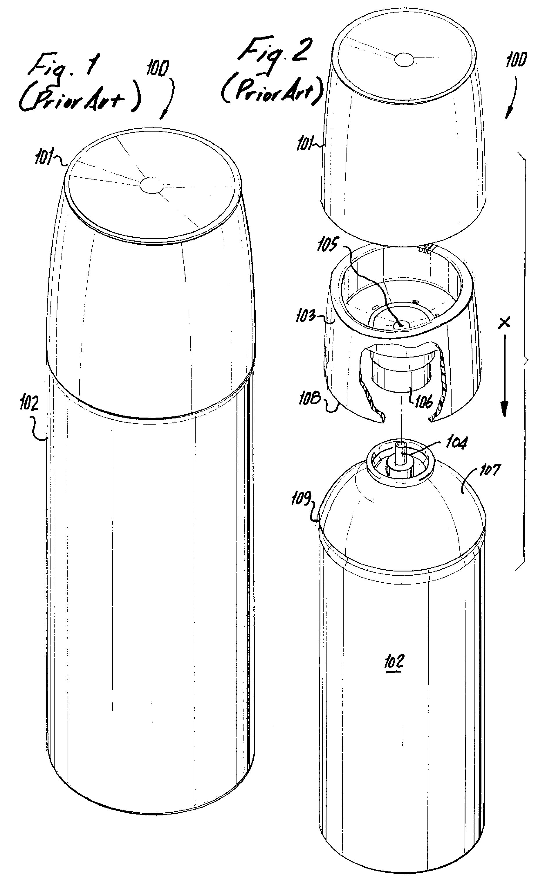
A related detriment is the unintended separation and potential loss of mouthpiece member 103 fully from assembly 100 upon removal of cover cap 101.
An additional detriment is the requirement for both (a) dual-handed use to operate securely, (b) the requirement for continual hand pressure along the bottle axis to actuate the valve assembly, and the inability to use personal assistive apparatus 100 in a hands-free condition, for example while resting.
As a consequence, the detriments of assembly 100 prohibit its use during high-energy sports such as climbing, mountaineering, and extreme skiing.
In sum, a conundrum exists in the industry between the need to supply oxygen and to supply sufficient lung volume to users that is yet unsatisfied in the industry.
No response to this need has been satisfactory to date.

Method used


Image

  • Personal assistive breathing apparatus
  • Personal assistive breathing apparatus
  • Personal assistive breathing apparatus

Examples


Embodiment Construction

[0052]Reference will now be made in detail to several embodiments of the invention that are illustrated in the accompanying drawings. Wherever possible, same or similar reference numerals are used in the drawings and the description to refer to the same or like parts or steps. The drawings are in simplified form and are not to precise scale or shape. For purposes of convenience and clarity only, directional terms, such as top, bottom, up, down, over, above, and below may be used with respect to the drawings. These and similar directional terms should not be construed to limit the scope of the invention in any manner. Furthermore, the words “connect,”“couple,” and similar terms with their inflectional morphemes do not necessarily denote direct and immediate connections, but also include connections through mediate elements or devices.

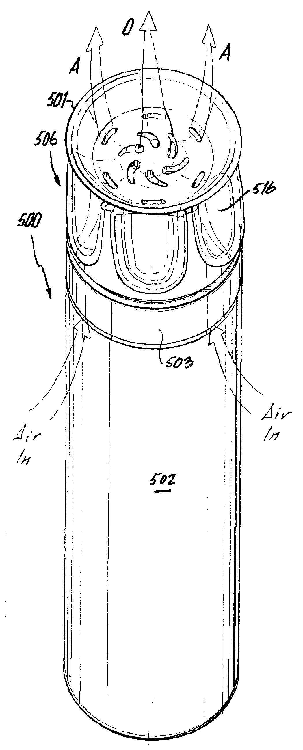
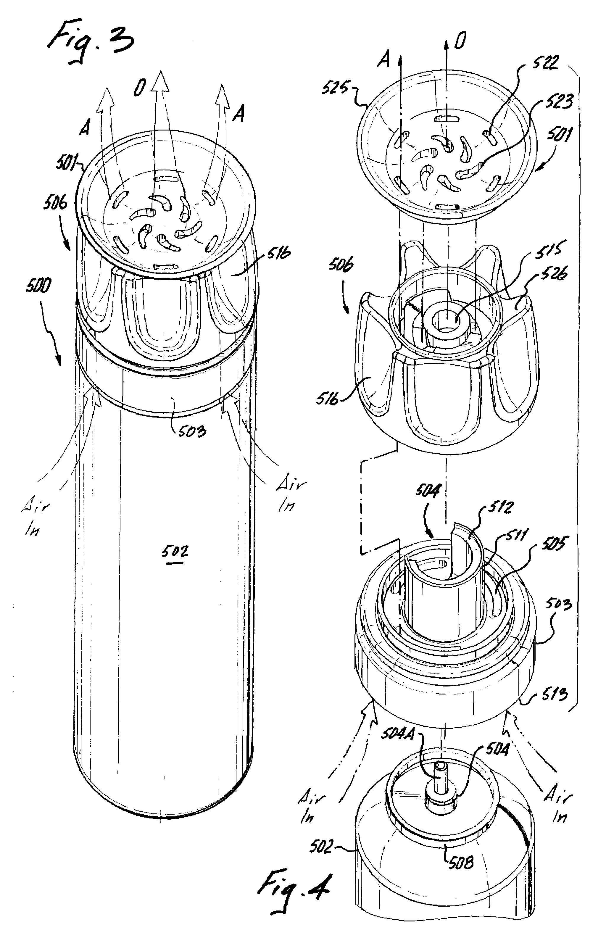
[0053]Referring now to FIGS. 3-4, a personal assistive breathing apparatus 500 includes an assembly fixably joined to a top portion of a gas container 5...


PUM


Abstract

The present invention relates to a personal use assistive breathing device wherein a can adaptor or bottle mounting member is secured to a bottle canister containing a pressurized gas. A mouth piece member retains an action knob positioned for actuating a stem valve on the bottle canister upon a rotation. During use the action knob is spaced away from the mouthpiece and air passages entrain ambient atmospheric air with the escaping pressurized gas. The action knob may be retained in the in-use position without continual pressure allowing hands-free use. During storage, the action knob is spaced in contact with the mouthpiece prohibiting unintended gas release and enabling ready handling without risk of gas-loss.

Description

BACKGROUND OF THE INVENTION[0001]1. Field of the Invention[0002]The present invention relates to an assistive breathing apparatus for sports or exercise use. More specifically, the present invention relates to a breathing apparatus that is employs a unique and secure motion for releasing stored gas and supplying both the stored gas and entrained ambient atmosphere to a user while enabling later secure storage without risk of unintended release.[0003]2. Description of the Related Art[0004]The related art involves a wide number of personal use air canisters or oxygen canisters that often include some form of mouth-mask or lip canister. Personal-use oxygen canisters are commonly used, for example to augment or assist blood-oxygen content during extreme sports activity or during a user's presence at a high-altitude / low oxygen partial-pressure condition, where recover of blood-oxygen content is a slow process.[0005]The use of oxygen canisters has been long known from high-altitude mounta...

Claims


Application Information

Patent Timeline
IPC IPC(8): A61M15/00A61M15/08
CPCA63B2213/005A62B7/00
Inventor STRATTON, KELSEY
Owner GO2
Learn More