Valve for a pressurized dispensing container

Active Publication Date: 2008-02-21
GUY CHEM CO LLC
View PDF3 Cites 18 Cited by
  • Summary
  • Abstract
  • Description
  • Claims
  • Application Information

AI Technical Summary

Benefits of technology

[0019] The embodiment disclosed is particularly adapted for dispensing a highly flowable product such shave gel and also a spray product such as an insecticide spray. In that embodiment, the sealing grommet has a recess in its base for receiving the valve button. The relationship between the button diameter and the grommet recess diameter is a slip fit. The result is that the walls of the recess assure stability of the valve by minimizing any tendency of the valve to tilt.
[0020] Recesses in the edge of the button allow product to travel past the button into the valve stem sidewall openings when the valve is open. It is important that the recesses in the button be at least equal in area to the valve stem openings so as to avoid further restriction on the flow of the product to be dispensed.

Problems solved by technology

This drop in pressure reduces the rate at which product is dispensed and is inconvenient for the user.
However, the use of a hydrocarbon causes environmental concerns.

Method used


Image

  • Valve for a pressurized dispensing container
  • Valve for a pressurized dispensing container
  • Valve for a pressurized dispensing container

Examples


Embodiment Construction

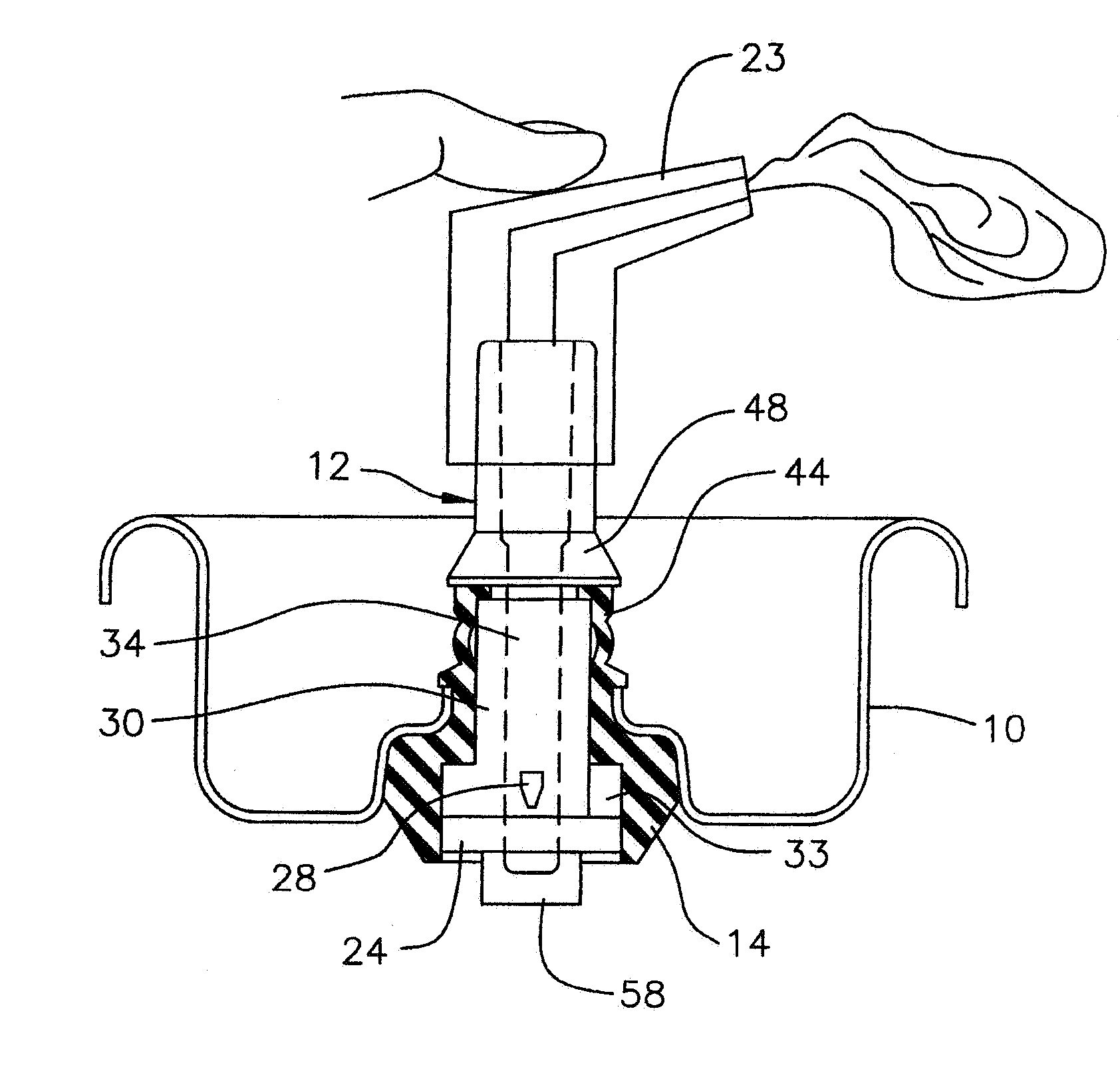
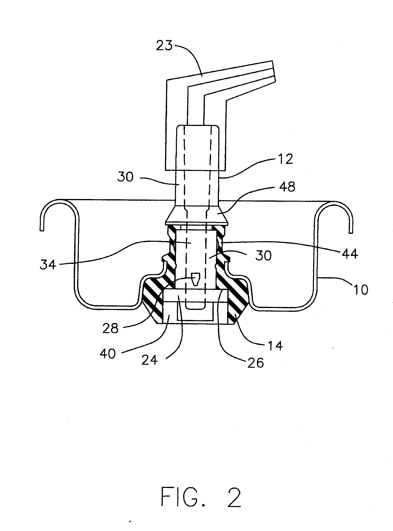
[0037] The FIGs. illustrate a single embodiment. As shown in FIG. 2, the three piece valve assembly is constituted by a mounting cup 10, a movable valve element 12 and a resilient annular sealing grommet 14. The valve element 12 has a button 24 which fits in a recess 40 in the base of the grommet 14.

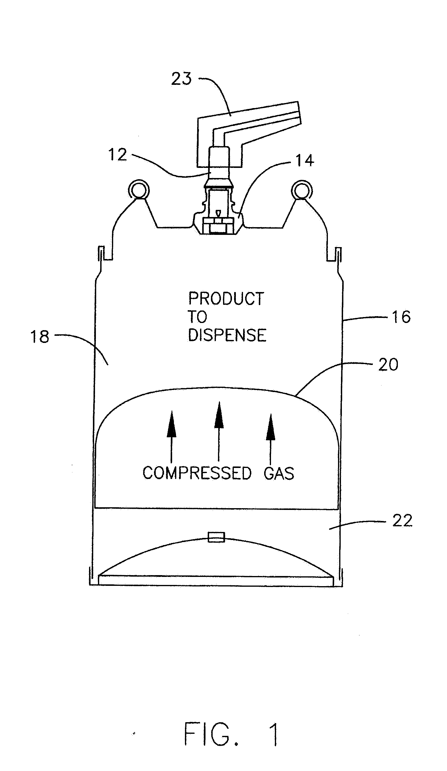
[0038] The mounting cup 10 performs a known function of mounting the valve assembly on top of the container 16 in which the product to be dispensed is contained. The product 18 to be dispensed is above the piston 20 which acts as a barrier between the product 18 and the gas under pressure in the lower chamber 22. The gas under pressure causes the piston 20 to apply pressure to the product 18. A piston 20 barrier is shown. But as is known in the art a collapsible bag barrier can be employed. A hand operated actuator 23 is mounted on top of the valve element 12.

[0039] The valve has a closed state in which the valve element 12 is in an upward position where a button 24 at the base of the ...


PUM


Abstract

An axially actuated valve for use in a pressurized container is controlled by a user to dispense the amount of product desired. The valve stem is moved in an up and down direction so that when dispensing, the user can control the amount of the valve openings that are in communication with the material to be dispensed. A resilient sealing grommet provides an interference fit around the lower part of the valve stem from the button up to the top of the valve stem openings. This interference fit effectively closes off the uncovered portion of the valve openings thereby permitting user control of the dispensing rate. The stem has openings partially tapered in the form of an inverted truncated pyramid to further facilitate user control of the dispensing of product.

Description

REFERENCE TO RELATED APPLICATIONS [0001] This application is a continuation-in-part of Ser. No. 11 / 334,716 filed Jan. 18, 2006, which in turn is a continuation-in-part of Ser. No. 10 / 882,625 filed Jun. 30, 2004, which in turn is a continuation of Ser. No. 10 / 816,969 filed Apr. 2, 2004, now abandoned, which in turn is a continuation of Ser. No. 10 / 285,238 filed Oct. 31, 2002, now abandoned; the entire disclosures of which are hereby incorporated by reference. BACKGROUND OF THE INVENTION [0002] This invention relates to a valve design for use in dispensing product from a pressurized container and more particularly to a valve whose design provides user control over the dispensing rate. This is particularly valuable where pressure in the container is developed from a gas, such as pressurized air or pressurized nitrogen, in which the pressure decreases as product is dispensed. [0003] Applicant's U.S. Pat. No. 5,785,301 and U.S. Pat. No. 6,425,503 and U.S. Pat. No. 6,340,103 are represent...

Claims


Application Information

Patent Timeline
IPC IPC(8): B65D83/00
CPCB65D83/64B65D83/48
Inventor SCHEINDEL, CHRISTIAN T.
Owner GUY CHEM CO LLC
Why Eureka
Try Eureka