Compliant Plate Seals for Turbomachinery

a technology of turbomachinery and seals, applied in the field of seals, can solve the problems of low stiffness, low efficiency of brush seals, and limits the maximum operable pressure differential to generally less than 1000 psi, and achieve the effect of reducing leakag

Inactive Publication Date: 2008-02-21
GENERAL ELECTRIC CO
View PDF29 Cites 33 Cited by
  • Summary
  • Abstract
  • Description
  • Claims
  • Application Information

AI Technical Summary

Benefits of technology

[0006] In an exemplary embodiment of the invention, a shaft seal reduces leakage between a rotating shaft and a static shell. The shaft seal includes a plurality of compliant plate members attached in facing relation to the static shell, where the compliant plate members define a seali...

Problems solved by technology

Brush seals, however, are effective only up to a certain pressure differential across the seal.
Because of the generally cylindrical geometry of the bristles, the brush seals tend to have a low stiffness in the axial direction, which limits the maximum operable pressure differential to generall...

Method used


Image

  • Compliant Plate Seals for Turbomachinery
  • Compliant Plate Seals for Turbomachinery
  • Compliant Plate Seals for Turbomachinery

Examples


Embodiment Construction

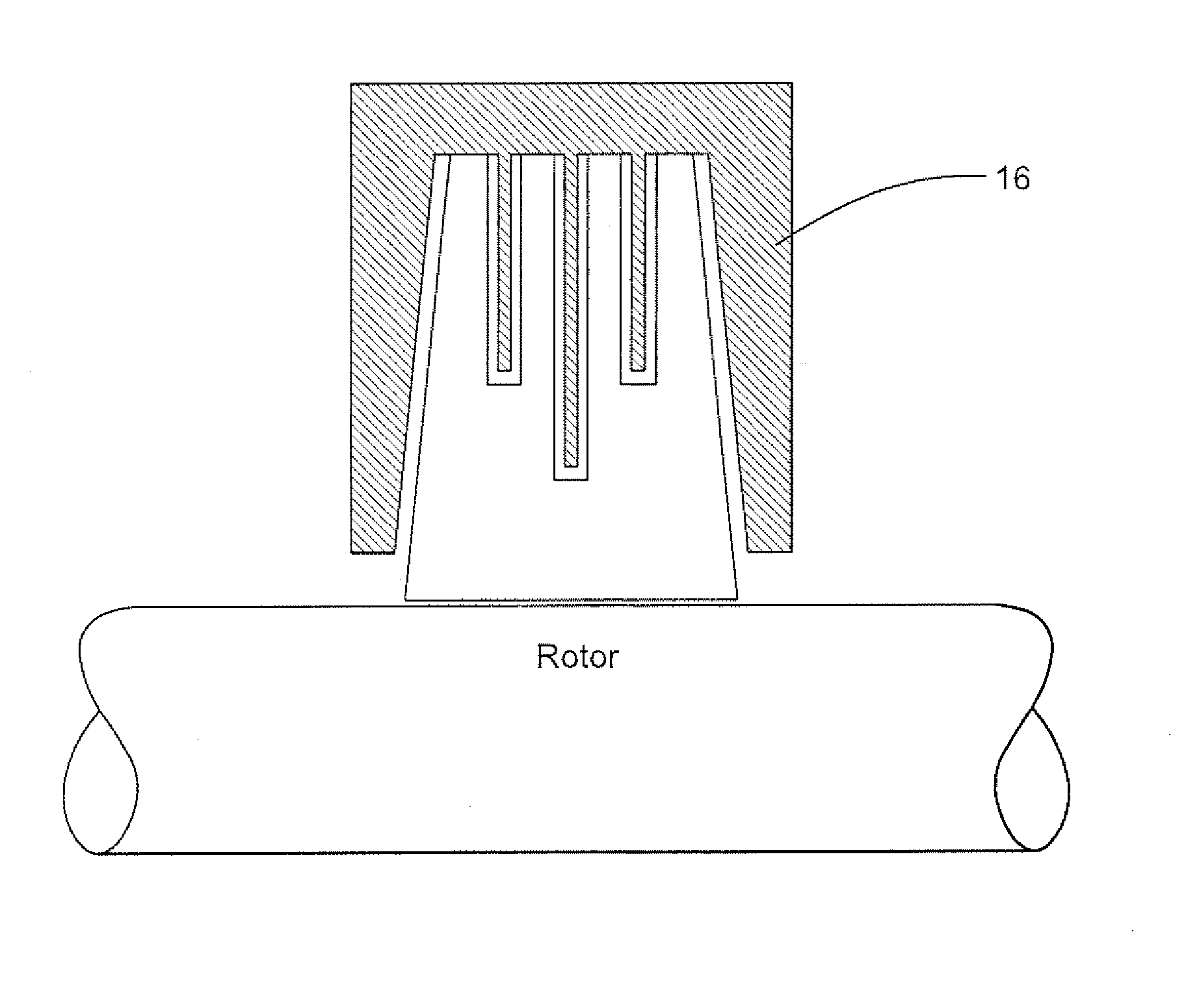
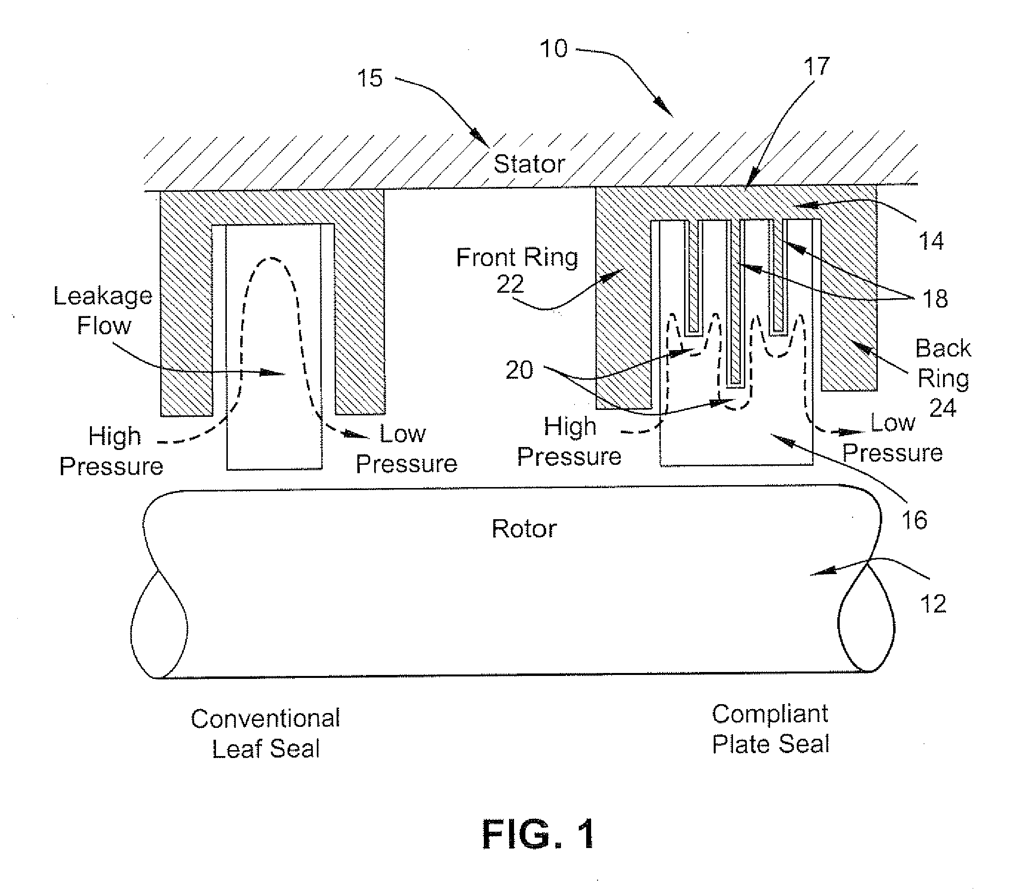
[0012] The improved compliant plate seal described herein achieves a structure that curtails the above-mentioned axial leakage seen in a conventional leaf seal by employing a geometry that includes features of a labyrinth seal. As noted, in a conventional leaf seal, because the leaves are packed tightly at the tips and loosely at the roots, axial leakage entering the leaf pack tends to flow / expand radially outward, then axially and finally converges as it exits the leaf pack.

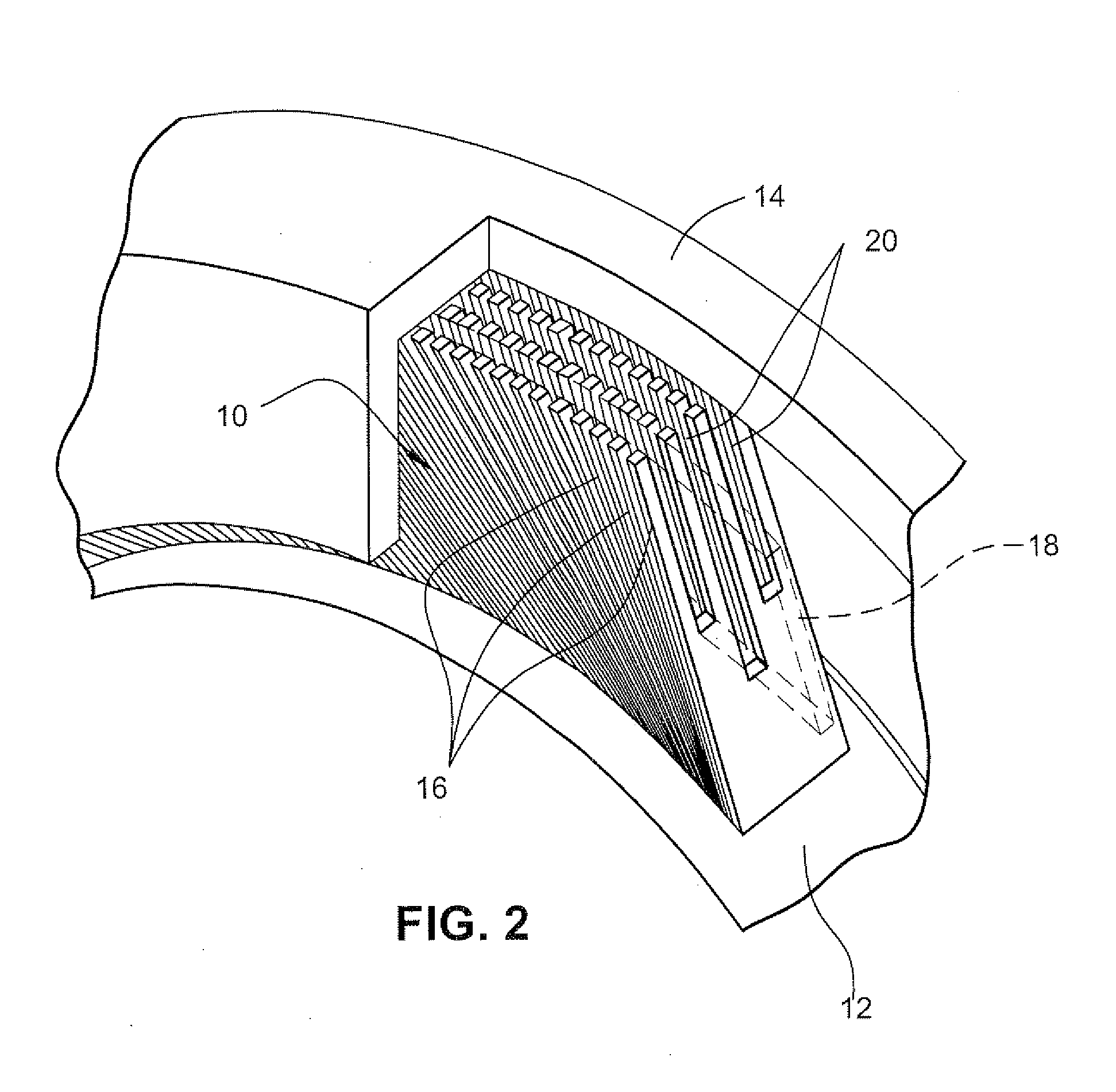
[0013] With reference to FIGS. 1 and 2, a shaft seal 10 serves to reduce axial leakage between a rotor 12, such as a rotating shaft, and a housing 14, attached to the turbine static shell 15. The shaft seal 10 is provided with a plurality of compliant plate members 16 secured at their roots in facing relation (i.e., face-to-face) to the housing 14. The compliant plate members 16 define a sealing ring between the housing 14 and the rotating shaft 12.

[0014] An axial flow resistance member 17 is disposed within t...


PUM

PropertyMeasurementUnit
Flow rateaaaaaaaaaa

Abstract

A shaft seal serves to reduce leakage between a rotating shaft and a static shell. The shaft seal includes a plurality of compliant plate members, each having a root and a tip. The compliant plate members are secured to the static shell at their root in facing relation. The tips of the compliant plate members define a sealing ring between the static shell and the rotating shaft. An axial flow resistance member is disposed within the compliant plate members and serves as a barrier to axial leakage flow between the compliant plate members.

Description

[0001] This application is a continuation of U.S. patent application Ser. No. 11 / 504,061, filed Aug. 15, 2006, pending, the entire contents of which are hereby incorporated by reference in this application.BACKGROUND OF THE INVENTION [0002] The invention relates to a sealing structure between a rotating component and a static component and, more particularly, to a compliant plate seal arrangement that additionally utilizes features of a labyrinth seal. [0003] Dynamic sealing between a rotor (e.g., rotating shaft) and a stator (e.g., static shell or casing) is an important concern in turbomachinery. Several methods of sealing have been proposed in the past. In particular, sealing based on flexible members has been utilized including seals described as leaf seals, brush seals, finger seals, shim seals, etc. [0004] A brush seal is comprised of tightly packed generally cylindrical bristles that are effective in preventing leakage because of their staggered arrangement. The bristles have...

Claims


Application Information

Patent Timeline
IPC IPC(8): F01D11/02
CPCF01D11/003F01D11/02F16J15/3292Y10T29/4932F05D2250/70F05D2250/13F05D2250/12F16J15/16
Inventor AWTAR, SHORYATURNQUIST, NORMAN ARNOLD
Owner GENERAL ELECTRIC CO
Why Eureka
Try Eureka