Steering apparatus
a technology of steering apparatus and steering mechanism, which is applied in the direction of apparatus for force/torque/work measurement, instruments, transportation and packaging, etc., can solve the problems of sensor failure, reduced detection accuracy, and slight time delay of steering mechanism, so as to improve steering feel, prevent problems, and reduce detection accuracy
- Summary
- Abstract
- Description
- Claims
- Application Information
AI Technical Summary
Benefits of technology
Problems solved by technology
Method used
Image
Examples
embodiment 1
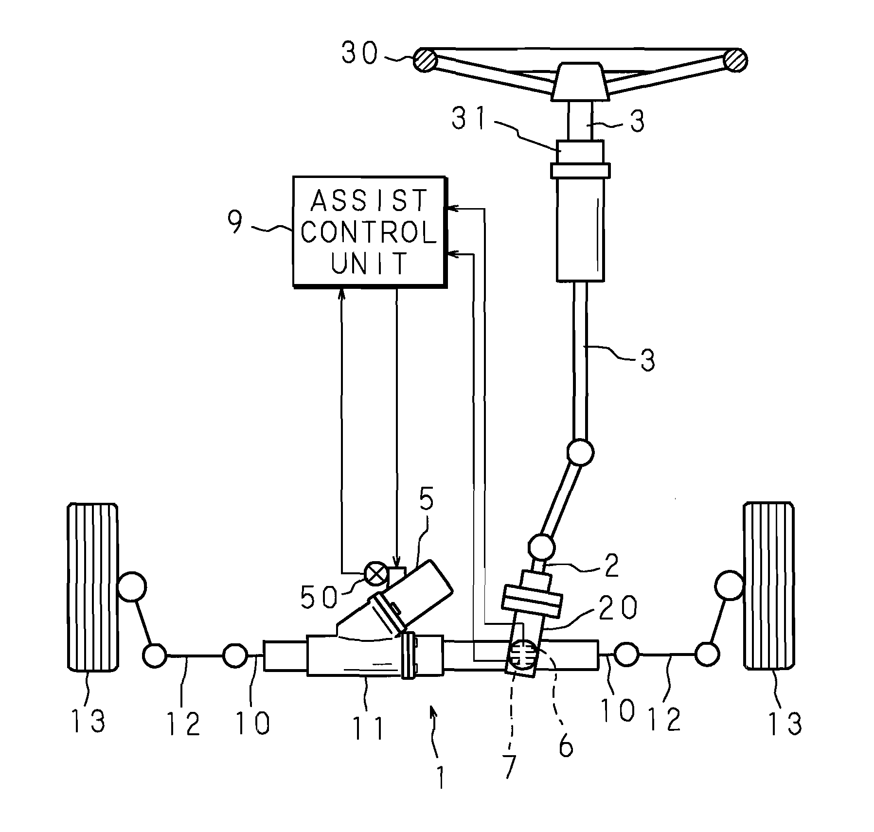
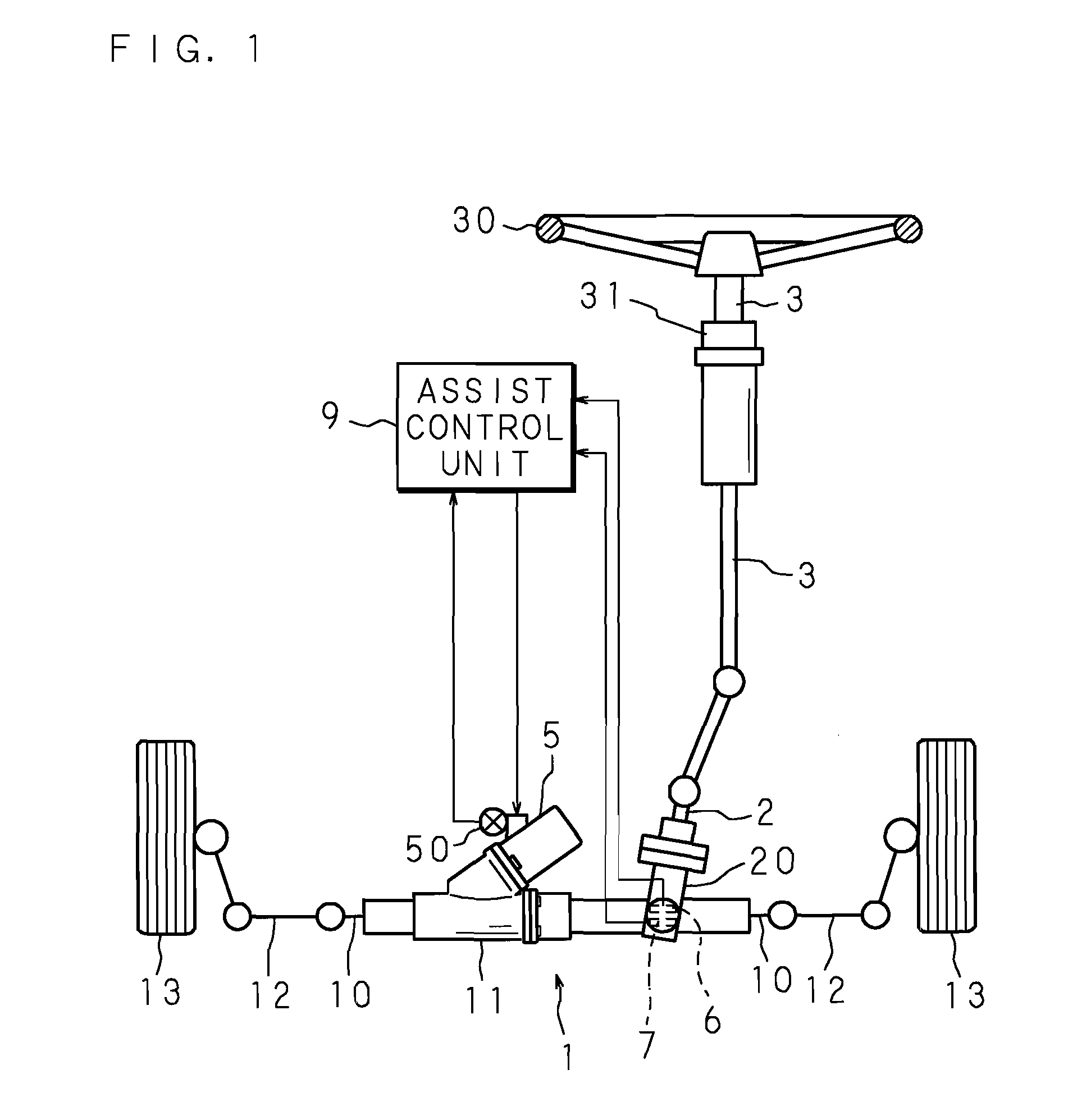
[0029]Hereinafter, Embodiments will be explained in detail based on the appended drawings. FIG. 1 is a schematic view showing a configuration of a steering apparatus according to the embodiments. The steering apparatus shown in FIG. 1 includes a rack-and-pinion-type steering mechanism, and is configured to be a rack-assist-type electric power steering apparatus.
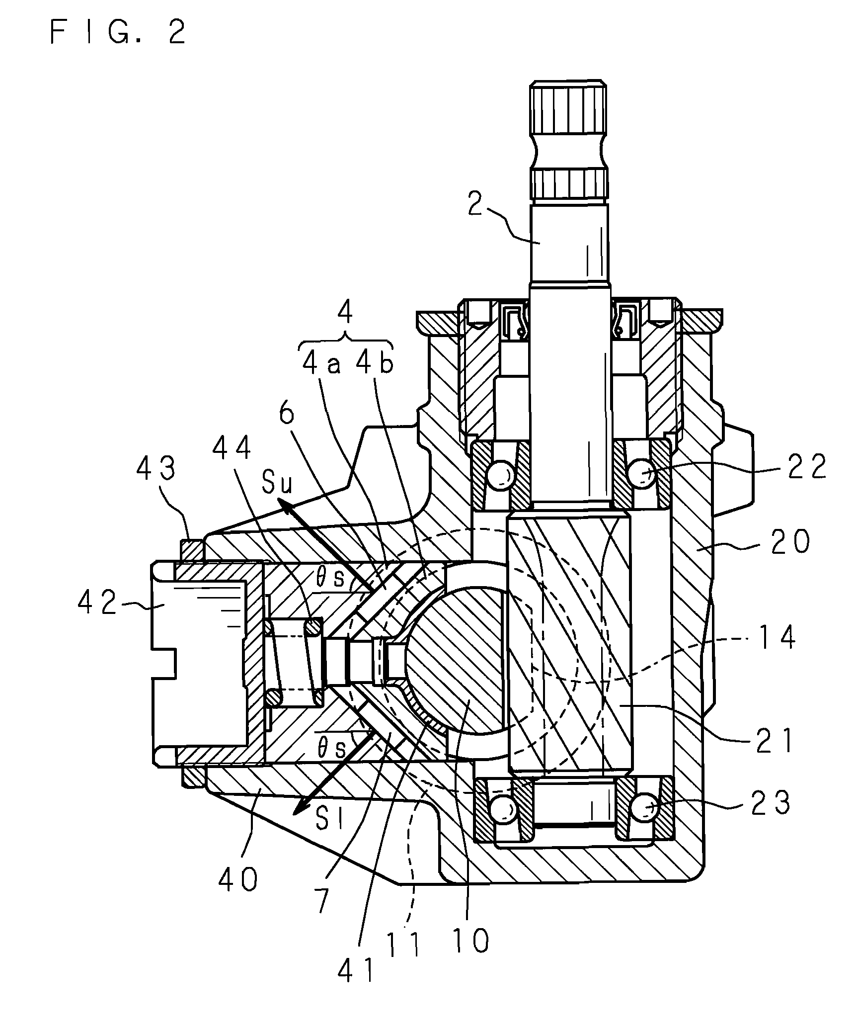
[0030]The rack-and-pinion-type steering mechanism 1 has a known configuration in which it includes a rack shaft 10 movably supported in the axial direction inside a rack housing 11 extending to the left-and-right direction of the vehicle body (not illustrated), and a pinion shaft 2 rotatably supported inside the pinion housing 20 which intersects with the rack housing 11 at an intermediate position of the rack housing 11.
[0031]Both ends of the rack shaft 10 which projects outside from the both sides of the rack housing 11 are coupled to front wheels 13 on the left and right sides as steerable wheels through respective tie rod...
embodiment 2
[0052]In the column-assist-type electric power steering apparatus, the assisting torque by the steering assist motor is included in the torque T applied to the pinion shaft 2. Therefore, in order to calculate the steering torque Th applied to the steering wheel 30, it is necessary to subtract the assisting torque from the torque T applied to the pinion shaft 2. The steering torque Th can be expressed as the following equation using the torque T applied to the pinion shaft 2 which can be calculated by Equation (3).
Th=T−Tm·α (5)
[0053]Here, Tm is a motor torque, and can be expressed by the product of a motor current Is and a torque constant Kt of the motor. α is a transmission ratio of a transmission means for reducing a rotation of an output shaft of the steering assist motor, and transmitting the reduced rotation to the steering column 3.
[0054]In the above Embodiments 1 and 2, it has been explained that the plane defined by the support yoke 4 and the rack shaft 10 is the plane inclu...
embodiment 3
[0057]FIG. 4 is a schematic view showing a configuration of a steering apparatus according to embodiments. The steering apparatus shown in FIG. 4 includes a rack-and-pinion-type steering mechanism, and is configured to be a rack-assist-type electric power steering apparatus.
[0058]The rack-and-pinion-type steering mechanism 1 has a known configuration in which it includes a rack shaft 10 movably supported in the axial direction inside a rack housing 11 extending to the left-and-right direction of the vehicle body (not illustrated), and a pinion shaft 2 rotatably supported inside the pinion housing 20 which intersects with the rack housing 11 at an intermediate position of the rack housing 11.
[0059]Both ends of the rack shaft 10 which projects outside from the both sides of the rack housing 11 are coupled to front wheels 13 on the left and right sides as steerable wheels through respective tie rods 12. Further, an upper end of the pinion shaft 2 which projects outside from one side of...
PUM
 Abstract
Description
Claims
Application Information
 - R&D
- Intellectual Property
- Life Sciences
- Materials
- Tech Scout
- Unparalleled Data Quality
- Higher Quality Content
- 60% Fewer Hallucinations
Browse by: Latest US Patents, China's latest patents, Technical Efficacy Thesaurus, Application Domain, Technology Topic, Popular Technical Reports.
© 2025 PatSnap. All rights reserved.Legal|Privacy policy|Modern Slavery Act Transparency Statement|Sitemap|About US| Contact US: help@patsnap.com


