Modem and method for switching operation modes thereof
Inactive Publication Date: 2008-02-21
HON HAI PRECISION IND CO LTD
6 Cites 3 Cited by
AI-Extracted Technical Summary
Problems solved by technology
Thus, the cost is...
Abstract
A modem (10) includes a signal tuner module (101), a signal processing module (103), and a mode switching module (105). The signal tuner module receives a radio frequency (RF) signal in a first operation mode, and converts the RF signal to an intermediate frequency (IF) signal according to the first operation mode. The signal processing module processes the IF signal to generate an error rate according to the first operation mode. The mode switching module determines whether the first operation mode is right according to the error rate, and switches from the first operation mode to a second operation mode when the first operation mode is not right. A method for switching operation modes thereof is also provided.
Application Domain
Broadband local area networksTelephonic communication +1
Technology Topic
Intermediate frequencyRadio frequency +6
Image
Examples
- Experimental program(1)
Example
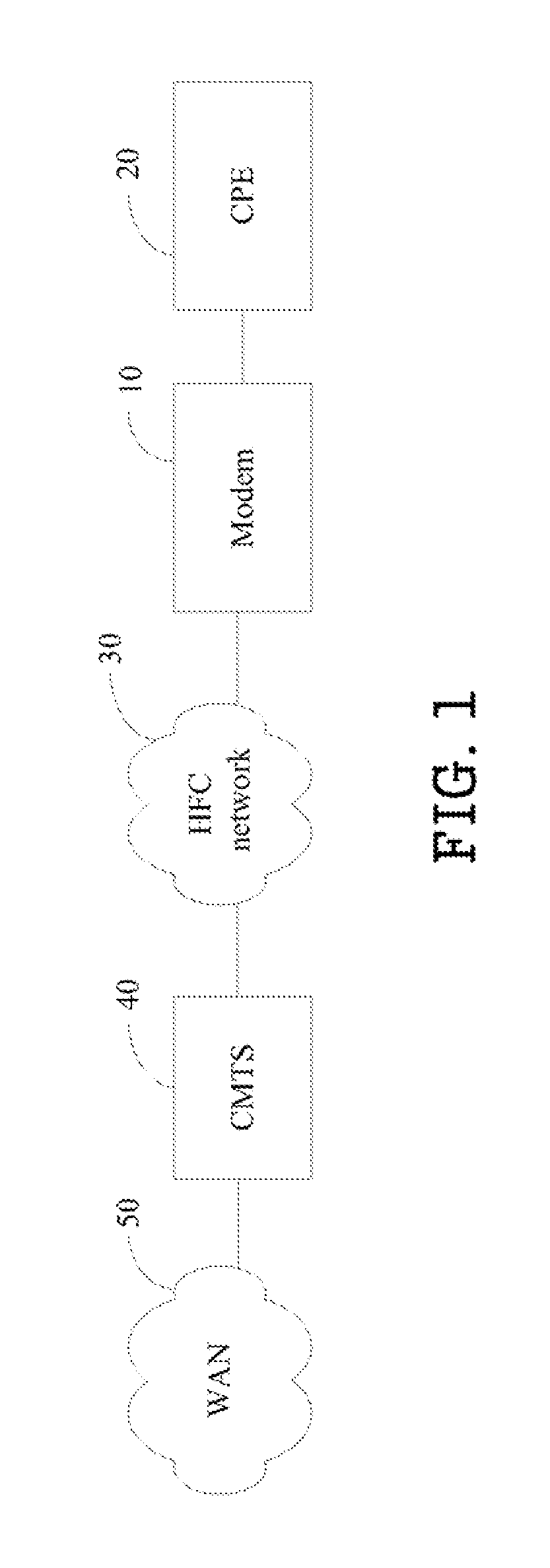
[0013]FIG. 1 is a schematic diagram of a data-over-cable system of an exemplary embodiment of the present invention. In the exemplary embodiment, the data-over-cable system includes a modem 10, a customer premises equipment (CPE) 20, a hybrid fiber coaxial (HFC) network 30, a cable modem termination system (CMTS) 40, and a wide area network (WAN) 50. In this embodiment, the modem 10 may be a cable modem, and the CPE 20 may be a personal computer. The modem 10 may be in a data over cable service interface specifications (DOCSIS) operation mode, a European DOCSIS (Euro-DOCSIS) operation mode, or a Japanese DOCSIS (J-DOCSIS) operation mode.
[0014]The CPE 20 is connected to the modem 10. The modem 10 is connected to the CMTS 40 via the HFC network 30. The CMTS 40 is connected to the WAN 50. The transmission path over the data-over-cable system is realized at the head-end by the CMTS 40, and at each customer location by the modem 10. Thus, the CPE 20 accesses the WAN 50 via the modem 10, the HFC network 30, and the CMTS 40. The CMTS 40 converts data received from the WAN 50 to RF signals, and then transmits the RF signals to the modem 10 via channels of the HFC network 30. The modem 10 scans the channels of the HFC network 30 to receive the RF signals.
[0015]In the exemplary embodiment, the modem 10 initially receives a radio frequency (RF) signal in a first operation mode, and converts the RF signal to an intermediate frequency (IF) signal according to the first operation mode. The modem 10 then processes the IF signal to generate an error rate according to the first operation mode, determines whether the first operation mode is right according to the error rate, and switches from the first operation mode to a second operation mode when the first operation mode is not right. In such way, the modem 10 works in more than one operation mode, namely more than one system with different specifications, and selects an applicable operation mode when multi system operators (MSO) switch from one system to another, for example, from a DOCSIS system to a Euro-DOCSIS system. In addition, modem manufacturers may manufacture the same modem for customers with different specification requirements.
[0016]FIG. 2 is a schematic diagram of functional modules of the modem 10 of an exemplary embodiment of the present invention. In the exemplary embodiment, the modem 10 includes a signal tuner module 101, a signal processing module 103, and a mode switching module 105. The modem 10 initially works in a first operation mode. The first operation mode may be a DOCSIS operation mode, a Euro-DOCSIS operation mode, or a J-DOCSIS operation mode.
[0017]The signal tuner module 101 receives a RF signal from a channel of the HFC network 30, and converts the RF signal to a first IF signal according to the first operation mode. In the exemplary embodiment, a frequency of the IF signal may be 4 MHz when the first operation mode is the DOCSIS mode, 5 MHz When the first operation mode is the Euro-DOCSIS mode, or 4 MHz When the first operation mode is the J-DOCSIS mode.
[0018]In other embodiments, the frequency of the IF signal in each operation mode may be different according to different tuner module architectures and demodulator implementations.
[0019]The signal tuner module 101 includes a mixer module 1010 and a gain control module 1012. The mixer module 1010 mixes the RF signal and a local oscillator (LO) signal to produce the first IF signal. The gain control module 1012 adjusts a gain of the first IF signal produced by the mixer module 1010.
[0020]The signal processing module 103 processes the first IF signal to generate a first error rate according to the first operation mode. In the exemplary embodiment, the first error rate is a forward error correction (FEC) error rate. The FEC may be compliant with Annex B of the international telecommunications union (ITU) J83 when the first operation mode is the DOCSIS mode, Annex A of the ITU J83 when the first operation mode is the Euro-DOCSIS mode, or Annex C of the ITU J83 when the first operation mode is the J-DOCSIS mode.
[0021]In other embodiments, the FEC in each operation mode may be compliant with different standards according to different requirements.
[0022]The signal processing module 103 includes an analog/digital (A/D) converter 1030, a demodulating module 1032, and an error correction module 1034. The A/D converter 1030 converts the IF signal to a digital signal. In the exemplary embodiment, the A/D converter 1030 converts the IF signal to the digital signal according to parameters such as a sampling rate corresponding to the frequency of the IF signal. The demodulating module 1032 demodulates the digital signal. The error correction module 1034 processes the demodulated digital signal to generate the first error rate according to the first operation mode.
[0023]The mode switching module 105 determines whether the first operation mode is right according to the first error rate, and switches from the first operation mode to a second operation mode when the first operation mode is not right. In the exemplary embodiment, the mode switching module 105 determines whether the first operation mode is right according to whether the first error rate is greater than a threshold error rate. If the first error rate is greater than the threshold error rate, the first operation mode is not right. In such case, the switching mode 105 switches from the first operation mode to a second operation mode. Otherwise, the first operation mode is right, and the modem 105 works in the first operation mode.
[0024]The signal tuner module 101 then converts the RF signal to a second IF signal according to the second operation mode. The signal processing module 103 processes the second IF signal to generate a second error rate according to the second operation mode. The mode switching module 105 determines whether the second operation mode is right according to the second error rate, and switches from the second operation mode to a third operation mode when the second operation mode is not right. In the exemplary embodiment, the first operation mode is selected from the group consisting of a DOCSIS operation mode, a Euro-DOCSIS operation mode, and a J-DOCSIS operation mode, the second operation mode is selected from the remaining two operation modes, and the third operation mode is the remaining one operation mode.
[0025]The signal tuner module 101 then converts the RF signal to a third IF signal according to the third operation mode. The signal processing module 103 processes the third IF signal to generate a third error rate according to the third operation mode. The mode switching module 105 determines whether the third operation mode is right according to the third error rate. If the third operation mode is right, the modem 10 works in the third operation mode. If the third operation mode is not right, the signal tuner mode 101 receives another RF signal from another channel of the HFC network 30, and the mode switching module 105 switches to the first operation mode.
[0026]FIG. 3 is a flowchart of a method for switching operation modes of an exemplary embodiment of the present invention.
[0027]In step S300, the signal tuner module 101 receives a RF signal in a first operation mode.
[0028]In step S302, the signal tuner module 101 converts the RF signal to an IF signal according to the first operation mode.
[0029]In step S304, the signal processing module 103 processes the IF signal to generate an error rate according to the first operation mode.
[0030]In step S306, the mode switching module 105 determines whether the first operation mode is right according to the error rate. If the first operation mode is right, the modem 10 works in the first operation mode.
[0031]If the first operation mode is not right, in step S308, the switching module 105 switches from the first operation mode to a second operation mode.
[0032]FIG. 4 is a flowchart of a method for switching operation modes of another exemplary embodiment of the present invention. In the exemplary embodiment, the modem 10 selects an applicable operation mode.
[0033]In step S400, the signal tuner module 101 receives a RF signal from a channel in a first operation mode.
[0034]In step S402, the signal tuner module 101 converts the RF signal to a first IF signal according to the first operation mode. In the exemplary embodiment, the mixer module 1010 mixes the RF signal and a local oscillator signal to produce the first IF signal. The gain control module 1012 adjusts a gain of the first IF signal produced by the mixer module 1010.
[0035]In step S404, the signal processing module 103 processes the first IF signal to generate a first error rate according to the first operation mode. In the exemplary embodiment, the A/D converter 1030 converts the IF signal to a digital signal. The demodulating module 1032 demodulates the digital signal. The error correction module 1034 processes the demodulated digital signal to generate the first error rate according to the first operation mode. In this embodiment, the first error rate is an FEC error rate.
[0036]In step S406, the mode switching module 105 determines whether the first operation mode is right according to the first error rate. In the exemplary embodiment, the mode switching module 105 determines whether the first operation mode is right according to whether the first error rate is greater than a threshold error rate. If the first error rate is greater than the threshold error rate, the first operation mode is not right. Otherwise, the first operation mode is right, and the modem 105 works in the first operation mode.
[0037]If the first operation mode is not right, in step S408, the mode switching module 105 switches from the first operation mode to a second operation mode.
[0038]In step S410, the signal tuner module 101 converts the RF signal to a second IF signal according to the second operation mode.
[0039]In step S412, the signal processing module 103 processes the second IF signal to generate a second error rate according to the second operation mode. Then the process goes to a node A.
[0040]FIG. 5 is a flowchart of the method for switching operation modes after the node A of FIG. 4.
[0041]In step S500, the mode switching module 105 determines whether the second operation mode is right according to the second error rate. If the second operation mode is right, the modem 10 works in the second operation mode.
[0042]If the second operation mode is not right, in step S502, the mode switching module 105 switches from the second operation mode to a third operation mode. In the exemplary embodiment, the first operation mode is selected from the group consisting of a DOCSIS operation mode, a Euro-DOCSIS operation mode, and a J-DOCSIS operation mode, the second operation mode is selected from the remaining two operation modes, and the third operation mode is the remaining one operation mode.
[0043]In step S504, the signal tuner module 101 converts the RF signal to a third IF signal according to the third operation mode.
[0044]In step S506, the signal processing module 103 processes the third IF signal to generate a third error rate according to the third operation mode.
[0045]In step S508, the mode switching module 105 determines whether the third operation mode is right according to the third error rate. If the third operation mode is right, the modem 10 works in the third operation mode.
[0046]If the third operation mode is not right, in step S512, the signal tuner module 101 receives another RF signal from another channel.
[0047]In step S510, the mode switching module 105 switches to the first operation mode. The process then goes back to step S402, the signal tuner module 101 converts the RF signal to another first IF signal according to the first operation mode. Then the above steps are repeated until the modem 10 switches to an applicable operation mode.
[0048]In another embodiment, the sequences of step S512 and step S510 may be exchanged.
[0049]Thus, the modem 10 can select an applicable operation.
[0050]While various embodiments and methods of the present invention have been described above, it should be understood that they have been presented by way of example only and not by way of limitation. Thus the breadth and scope of the present invention should not be limited by the above-described exemplary embodiments, but should be defined only in accordance with the following claims and their equivalents.
PUM


Description & Claims & Application Information
We can also present the details of the Description, Claims and Application information to help users get a comprehensive understanding of the technical details of the patent, such as background art, summary of invention, brief description of drawings, description of embodiments, and other original content. On the other hand, users can also determine the specific scope of protection of the technology through the list of claims; as well as understand the changes in the life cycle of the technology with the presentation of the patent timeline. Login to view more.