Escalatory Reactive Call Routing

a call routing and reactive technology, applied in the field of intelligent call routing systems, can solve the problems of a call center system, a call center that is not operating normally, and the range of switches is limited, and the routing that can be done is very limited

Inactive Publication Date: 2008-02-21
SHTIVELMAN YURI +10
View PDF11 Cites 19 Cited by
  • Summary
  • Abstract
  • Description
  • Claims
  • Application Information

AI Technical Summary

Benefits of technology

[0024] In embodiments of the present invention improvements over conventional systems and methods are provided, not the least of which is a way to use systems comprising equipment from different manufacturers in ways that are machine independent. Further, methods are provided that reduce call-waiting time in such systems, that improve efficiency, and that provide services at an improved cost efficiency compared to prior art systems.
[0027] In various embodiments of the invention, by using the sequential method, the number of destination numbers required to be assigned to each call center for the purpose of directing rerouted calls is minimized.

Problems solved by technology

If the call center consists of just a central switch and connected telephone stations, the routing that can be done is very limited.
Switches, although increasingly computerized, are limited in the range of computer processes that may be performed.
Even with present levels of CTI there are still problems in operating such call centers, or a system of such call centers.
Other difficulties accrue, for example, when there are hardware or software degradations or failures or overloads in one or more parts of a system.
Still other problems accrue due to known latency in conventional equipment.
Further to the above, IPNT systems at the time of the present patent application are much less sophisticated in provision of intelligent routing, parallel data transfer, supplemental data provision to agents, and the like.

Method used


Image

  • Escalatory Reactive Call Routing
  • Escalatory Reactive Call Routing
  • Escalatory Reactive Call Routing

Examples


Embodiment Construction

General Description

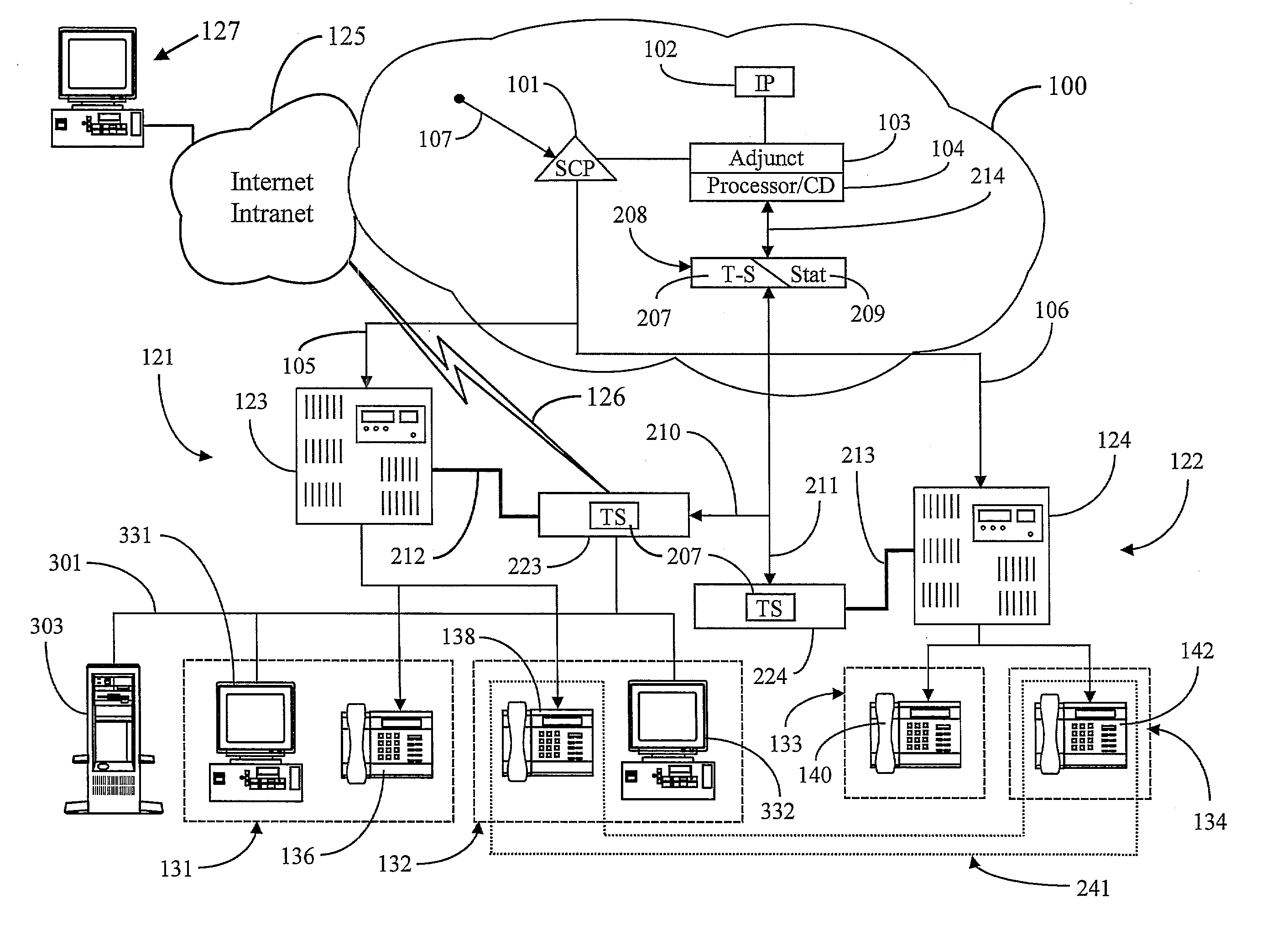
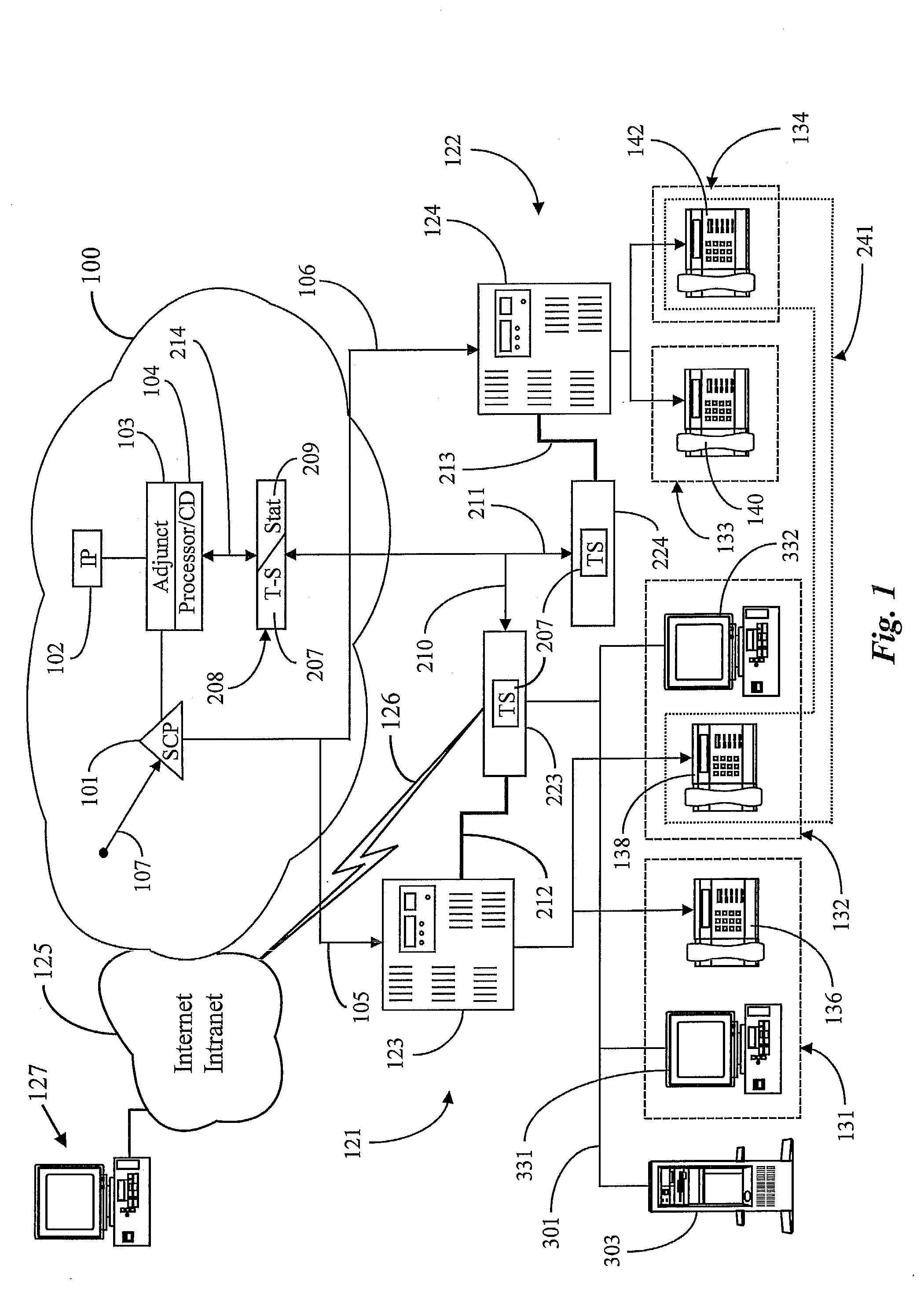
[0043]FIG. 1 is a system diagram of a call-routing system according to a preferred embodiment of the present invention, comprising two call centers 121 and 122. In this embodiment there may be many more than the two call centers shown, but two is considered by the inventors to be sufficient to illustrate embodiments of the invention. Each of call centers 121 and 122 includes a telephony switch (switch 123 for center 121 and switch 124 for center 122) providing routing to individual agent stations.

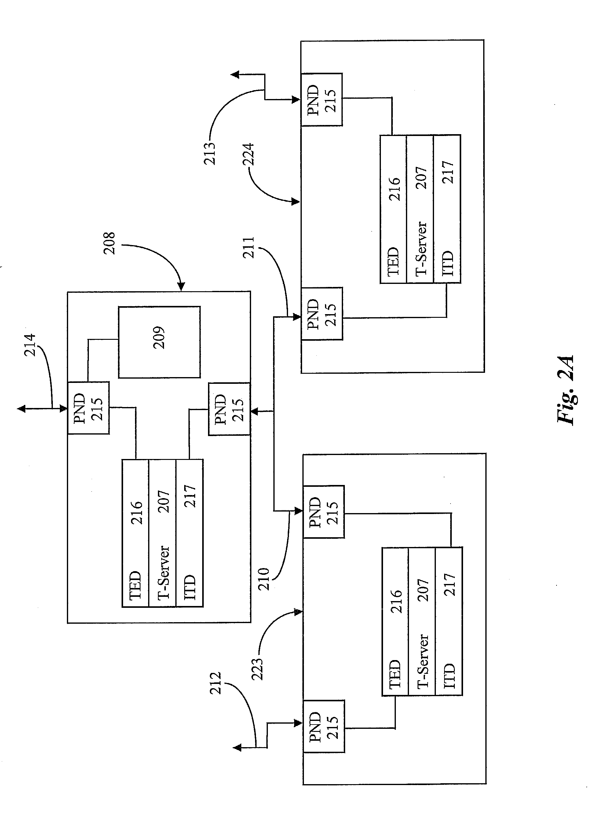
[0044] Call centers 121 and 122 in FIG. 1 are CTI-enhanced by virtue of a processor connected by a high-speed data link to the associated call center switch. At call center 121, processor 223 is connected by link 212 to switch 123, and at call center 122, processor 224 is connected to switch 124 by link 213. Each processor 223 and 224 includes an instance of a CTI application 207 known to the inventors as T-Server (T-S) 207. Further, each processor 223 and 224 at each ...


PUM


Abstract

A computerized telephony call center for serving a customer base has a central switch connected to a plurality of telephones at operator workstations and adapted to route calls to individual ones of the telephones, and also connected to a public switched telephone network, and a first processor connected to the central switch by a high-speed data link and to the telephone network by a digital network connection. The first processor is adapted to monitor transactional activity of the central switch, to process the activity information according to selected routines in the processor, and to communicate processed information to a second processor over the digital network connection. The digital network connection may be a TCP\IP connection. In a preferred embodiment the first processor is connected by a local area network (LAN) to network interfaces including a video display unit (VDU) and input apparatus proximate individual ones of the plurality of telephones connected to the central switch. In some embodiments the LAN is also connected to a data server running an instance of a database. In other embodiments the call center, and other similar call centers are all part of a call routing system wherein calls are routed from Service Control Points to call centers over telephone lines, and data is routed to the call centers over a separate digital network connection between processors coupled to the Service Control Points and to the call center central switches. In various embodiments aspects of the invention apply to Internet protocol network telephony (IPNT) calls as well as to conventional telephony calls.

Description

CROSS-REFERENCE TO RELATED DOCUMENTS [0001] The present patent application is a Continuation application of copending patent application Ser. No. 08 / 948,530, filed Oct. 9, 1997, which is a divisional application of Ser. No. 08 / 928,410, filed Sep. 12, 1997 (now U.S. Pat. No. 6,064,667), which is a CIP of Ser. No. 08 / 866,357 filed on Feb. 10, 1997, which is a CIP of application Ser. No. 08 / 802,660. The present application is also a Continuation of applications having the Ser. No. 09 / 096,729 filed Jun. 11, 1998, Ser. No. 09 / 574,315 filed May 19, 2000, Ser. No. 09 / 592,182 filed Jun. 12, 2000, Ser. No. 09 / 659,933 filed Sep. 12, 2000, and Ser. No. 09 / 561,139 filed Apr. 28, 2000. The prior applications are all incorporated herein in their entirety by reference.FIELD OF THE INVENTION [0002] The present invention is in the area of telephone call processing and switching, and pertains more particularly to intelligent call-routing systems. BACKGROUND OF THE INVENTION [0003] Telephone call proc...

Claims


Application Information

Patent Timeline
Patent Type & Authority Applications(United States)
IPC IPC(8): H04M3/00H04M3/51
CPCG06Q10/107H04M7/0027H04M3/5237H04M3/5191
Inventor SHTIVELMAN, YURIMILOSLAVSKY, ALECBONDARENKO, OLEGNEYMAN, IGORGISBY, DOUGLASCRONIN, PAULTUROVSKY, OLEGKISHINSKY, KONSTANTINANISIMOV, NIKOLAYPOGOSSIANTS, GREGORYPOSTUPALSKI, PAVEL
Owner SHTIVELMAN YURI
Why Eureka
Try Eureka