Endoscopic surgical tool

a surgical tool and endoscope technology, applied in the field of endoscopic instruments, can solve the problems of bulky instrumentation and fragile endoscopes, and achieve the effects of better durability, better visualization, and more precise instruments

Active Publication Date: 2008-02-21
MICROAIRE SURGICAL INSTR
View PDF18 Cites 87 Cited by
  • Summary
  • Abstract
  • Description
  • Claims
  • Application Information

AI Technical Summary

Benefits of technology

[0017]Fiber optic endoscope that allows for the camera and light cable to be connected remotely which makes for a more precise instrument and offers better durability than a rod lens endoscope
[0018]Retractor to provide better visualization during the dissection, guide the instrument as it dissects, and provide external sighting for correct location of the dissection.

Problems solved by technology

They also utilize rod lens endoscope technology that makes the instrumentation bulky and the endoscopes fragile.

Method used


Image

  • Endoscopic surgical tool
  • Endoscopic surgical tool
  • Endoscopic surgical tool

Examples


Embodiment Construction

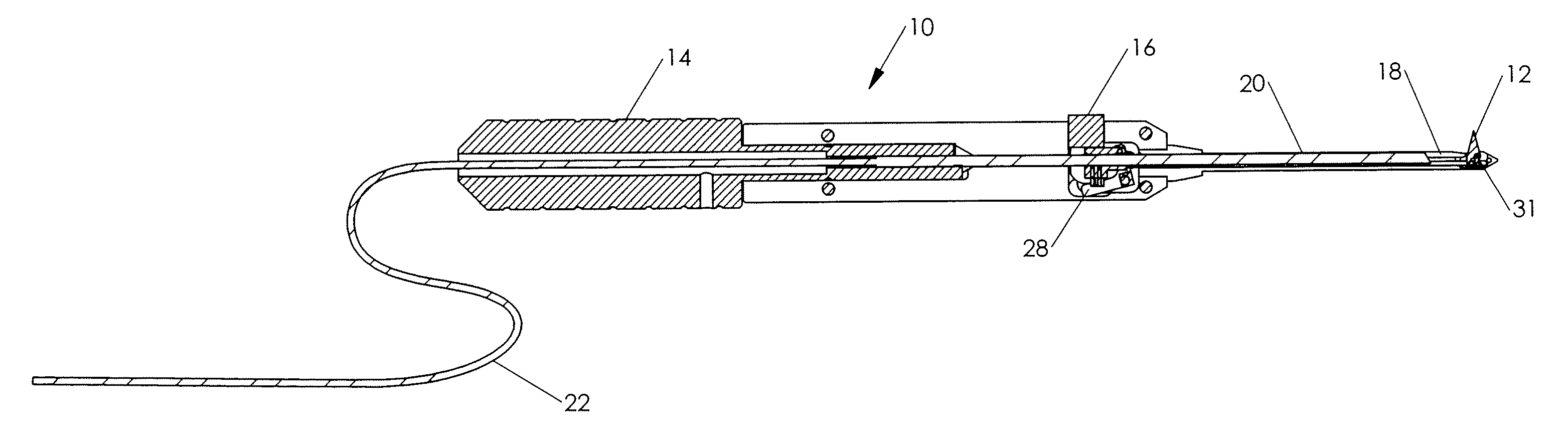
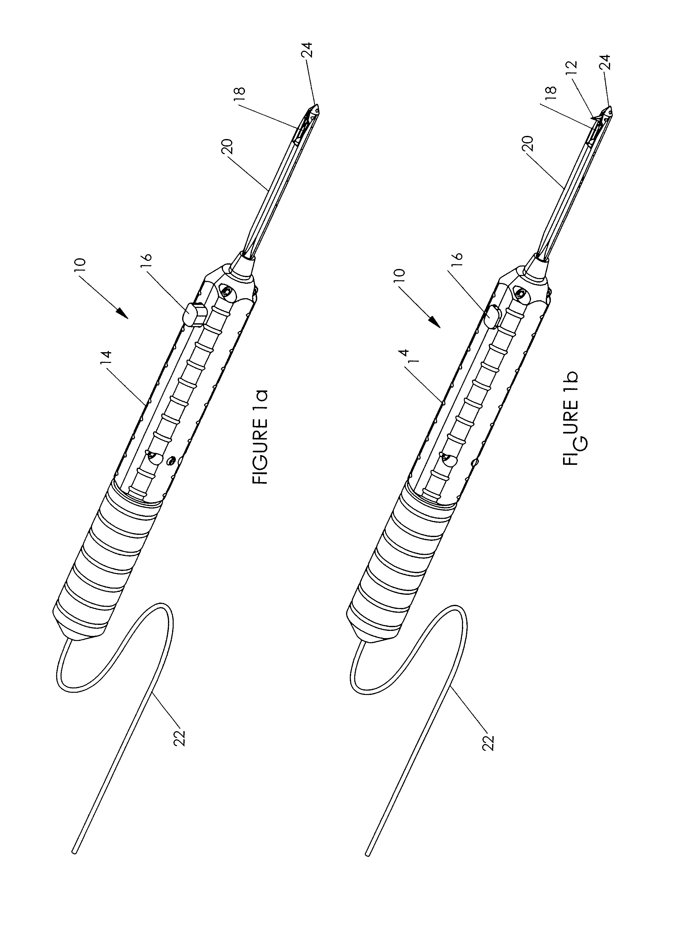
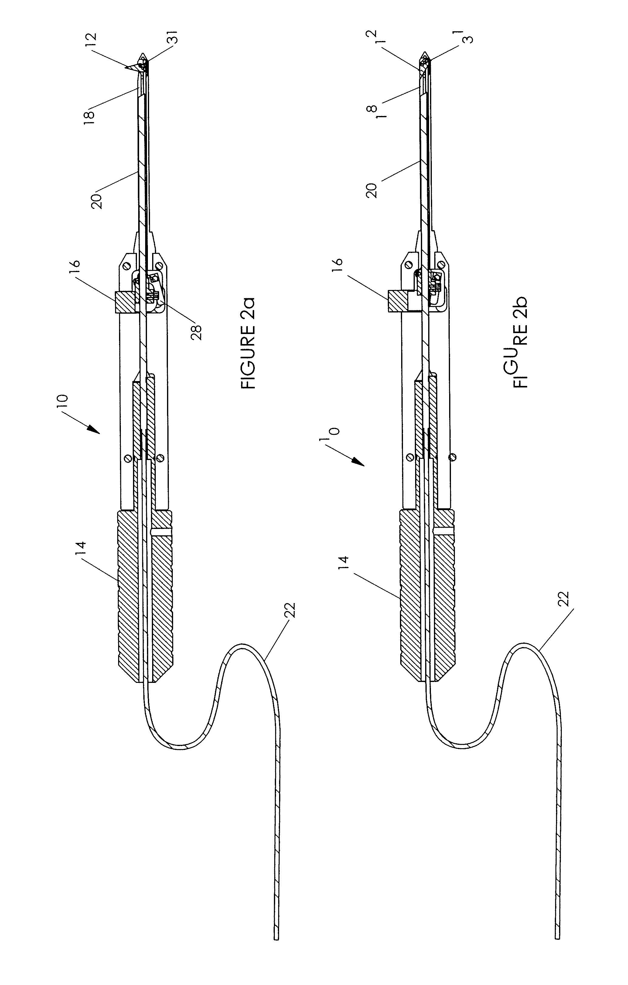
[0026]Referring now to the drawings, and more particularly to FIGS. 1a and 1b, there is shown a pencil grip style endoscopic tool 10. The tool 10 has features which are similar to parts of the endoscopic tools described in U.S. Pat. No. 4,962,770, U.S. Pat. No. 4,963,147, U.S. Pat. No. 5,089,000 and U.S. Pat. No. 5,306,284 to Agee, each of which are herein incorporated by reference; however, the tool 10 is generally smaller in size, uses different lighting and imaging technologies, and has a blade 12 which cuts in two directions. The tool 10 has a handle 14, with a button actuator 16. As can be seen from a comparison of FIG. 1a and FIG. 1b, when the actuator 16 is depressed by the surgeon using his or her thumb or by other means towards the handle 14, the blade 12 is deployed from the lateral opening 18 located near the end of the probe 20.

[0027]A fiber optic cable 22 extends through the handle 14, to the opening 18 near the end of the probe 20. The fiber optic cable 22 allows light...


PUM


Abstract

An endoscopic tool utilizes a fiber optic system for illuminating and imaging ligaments or other tissue which are to be cut. Illumination and imaging is performed above a lateral opening at the distal end of a probe that is inserted into an incision point. Preferably, a two edged blade which can be moved in both the distal to proximal direction and the proximal to distal direction is selectively deployable from of the lateral opening at the distal end of the probe. The endoscopic tool is small in size, and preferably includes a pencil grip with a button actuator for deploying the two edged cutting blade. A wire actuator that fits into a slot in the bottom of the deployable blade, can be nested with the fiber optic cable such that the cross sectional area of the probe is reduced. Alternatively, a tube concentric with the fiber optic cable can be used as the mechanism for actuating the blade or other device. The surgeon can observe cutting of the ligament or other tissue as he moves the endoscopic tool in either or both the forward or reverse direction on a display screen which is operatively connected to the fiber optic system. A retractor can be used in conjunction with the endoscopic tool to lift tissue where dissection is desired, and to function as a guide for the blade.

Description

BACKGROUND OF THE INVENTION[0001]1. Field of the Invention[0002]The present invention generally relates to endoscopic instruments, and is particularly related to surgical tools and procedures which can be used for the release of the transverse carpal ligament, as well as in other applications.[0003]2. Background Description[0004]Examples of surgical tools which are useful for inspecting and manipulating tissues (e.g., cutting of the transverse carpal ligament) in a body cavity are described in U.S. Pat. No. 4,962,770 to Agee, U.S. Pat. No. 4,963,147 to Agee, U.S. Pat. No. 5,089,000 to Agee, and U.S. Pat. No. 5,306,284 to Agee, each of which are herein incorporated by reference. The Agee patents show a probe which houses both a lens system and a selectively deployable blade. The lens system is used to illuminate and image tissue located above an opening in a top surface area of the probe near the probe's distal end. A pistol grip is provided which allows a surgeon to selectively depl...

Claims


Application Information

Patent Timeline
Patent Type & Authority Applications(United States)
IPC IPC(8): A61B17/32
CPCA61B2019/5206A61B17/320036A61B2090/306
Inventor WELBORN, KENNETH W.
Owner MICROAIRE SURGICAL INSTR
Why Eureka
Try Eureka