
Footwear cover

a technology for shoes and limbs, applied in the field of shoes covers, can solve the problems of liquid adding undesirable weight, affecting the performance of the shoe and its wearer, and affecting so as to maintain the function of the shoe and the wearer's limbs

Inactive Publication Date: 2008-02-28
HOCH ALLAN
View PDF18 Cites 21 Cited by
  • Summary
  • Abstract
  • Description
  • Claims
  • Application Information

AI Technical Summary

Benefits of technology

"The present invention is a footwear cover that protects shoes and other footwear from liquid, such as rain. The cover is designed to maintain the function of the shoe and the wearer's limbs as much as possible. It has a predominantly open sole that allows for maximum preservation of the shoe's function. The cover can be secured to the shoe using elastic straps or bands, toe or heel pockets, or other securing attachments that pass about the shoe's arch or between the sole treads or spikes. The cover is lightweight, flexible, and limits the entrance of liquid while maintaining its effectiveness."

Problems solved by technology

However, during sporting events or related activities that occur in all types of weather, especially weather involving precipitation, sports shoes and the wearer's corresponding limbs are vulnerable to getting wet.
At least two disadvantages can result from liquid added to a shoe, sock, or other related apparel that immediately affects the performance of the shoe and its wearer; the liquid adds undesirable weight, and increases the potential for bodily injury (e.g., blisters).
Ultimately, this can compromise the stability of a limb on the ground, and in foul weather, slick surfaces may further compound this instability.
Such a footwear covering is disadvantageous when the footwear cover is donned in situations where there is a need for greater or quicker movement of the lower limbs.
Furthermore, this type of cover, when subjected to these more involved movements, would be highly susceptible to splitting, cracking, or general breakdown especially in the ankle region and toe pocket.
Another disadvantage of the patent '778 design is that its vertical style slit opening with adjacent closure straps offers little protection from liquids that can enter between the adjacent edges of the covering's two sides.
This problem is further compounded during weather with precipitation because liquid may easily pass through the cover's slit opening when a wearer's heel region, and thus the slit opening, is positioned horizontally or near horizontally (as happens when the wearer's knee is flexed while walking, and more so while running).
First, a user's ability to use the same cover with another shoe, which has a differently shaped sole, is severely limited.
The spacing or location of the fasteners is unlikely to be consistent between sports shoes of different sizes and shapes, thus making it difficult to use one cover with multiple, different shoes.
Second, the cover, including all of its components, is not easily or completely removable when not in use.
Removing the sides of the fastener tapes that are affixed to the shoe sole diminishes their future ability to attach properly to the sole.
The reattachment and realignment of the corresponding hook and loop fastener sides would also be a tedious task each time the wearer decides to reuse the cover.
Third, the hook and loop attachment system has functional limitations due to its location on the shoe sole.
For example, debris can become trapped in the hooks or loops of the fasteners, thereby diminishing its attachment qualities.
The presence of an affixed adhesive structure that is not meant to compress will either diminish the sole's cushioning capability, or have its attachment to the sole adversely affected by each compression of the sole.
Another disadvantage of the footwear cover of the '895 patent is the rear entry closure and expanding pleats system in that it creates undesirable bunching and / or bulk of the cover material at a location where greater freedom of motion is essential.
The combination of the above described attributes of the '895 patent design and the expected movements of the ankle region will likely lead to discomfort of, or even injury to, the wearer at the ankle region.
This potential hazard would be compounded further due to the vertical direction of the hook and loop attachment system disclosed in the '895 patent.

Method used


Image

  • Footwear cover
  • Footwear cover
  • Footwear cover

Examples


Embodiment Construction

[0025]The present invention will now be described more fully hereinafter with reference to the accompanying drawings, in which preferred embodiments of the invention are shown. This invention may, however, be embodied in many different forms and should not be construed as limited to the illustrated embodiments set forth herein. Rather, these illustrated embodiments are provided so that this disclosure will be thorough and complete, and will fully convey the scope of the invention to those skilled in the art.

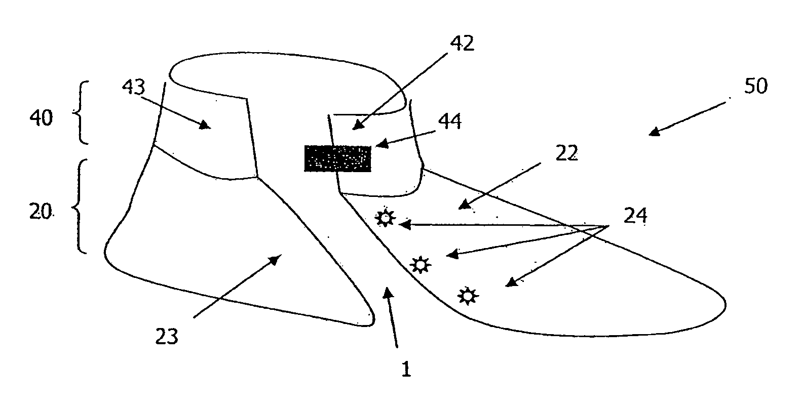
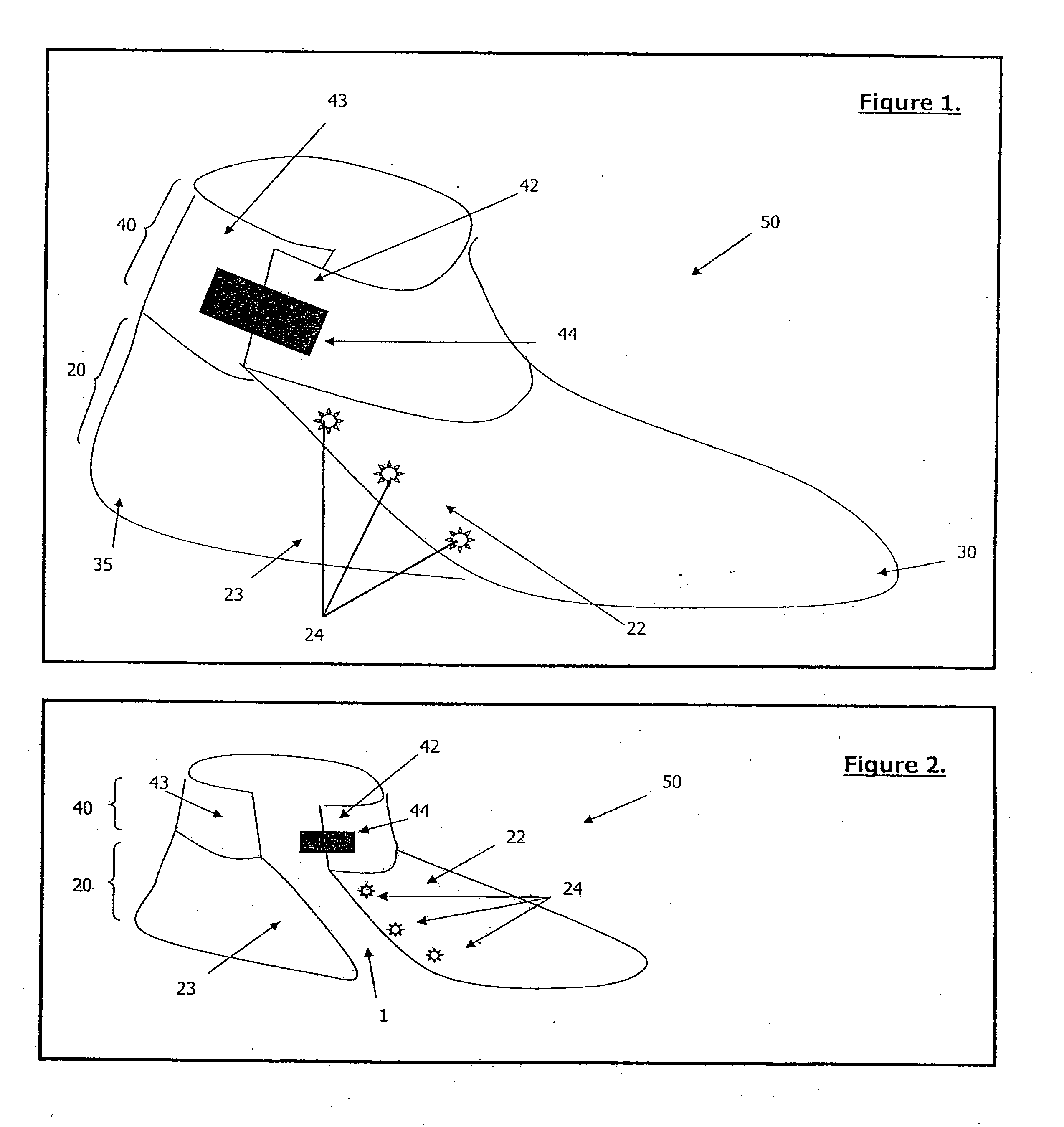
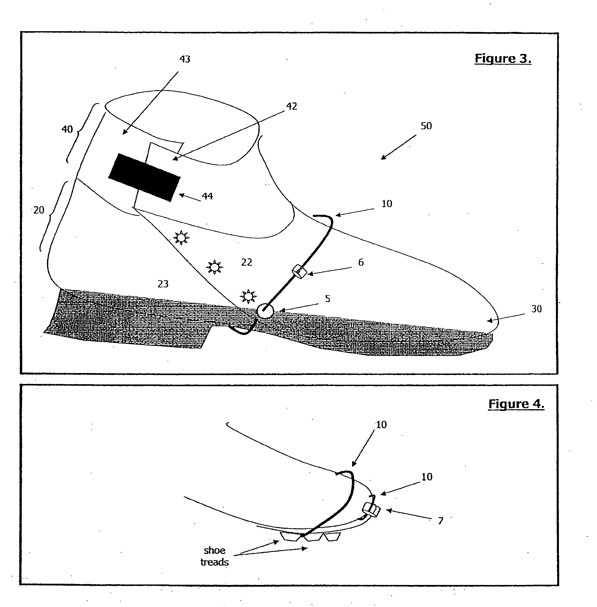
[0026]As seen in the embodiment depicted in FIG. 1, the footwear cover 50 has two main parts: an upper part 40 with an overlapping portion 42 and an overlapped portion 43, and a lower part 20 with an overlapping portion 22 and an overlapped portion 23. The front portion 30 and heel portion 35 will correspond to the toe and heel regions of footwear, respectively. The lower part 20 primarily covers the shoe upper (the portion of a shoe that covers the sides and top of a foot and at...


PUM


Abstract

A shoe cover may protect the footwear, enclosed foot, and adjacent parts of the lower limb from many hazards including liquids, especially precipitation such as rain, sleet, or snow. The disclosed footwear cover comprises two main parts: a lower part without a sole that covers the upper and heel of the shoe, and an upper part that covers the lower limb at or above the ankle. The lower part is secured to the shoe by one or more securing members that may pass around the sole of the shoe, a toe pocket, a securing member adapted to accommodate the treads of a shoe if present, or by an attachment on the shoe itself. The footwear cover is secured about the lower limb of the user by a strap or other fastener on the upper part of the footwear cover.

Description

BACKGROUND OF THE INVENTION[0001]1. Field of the Invention[0002]The present invention relates to footwear covers used to protect footwear, more particularly, to footwear covers that may be used to protect sports shoes.[0003]2. Background of the Invention[0004]Footwear covers—spats, gaiters, and the like—have been designed for various types of footwear to protect the footwear and the wearer's limb from potential damage, soiling, or from any other undesirable occurrence related to the use of the footwear. The footwear itself is usually designed to enhance, or at least to not impede the function of the wearer and the involved limbs. For example, sports shoes are designed to have attributes such as formfitting, lightweight, flexible, good surface traction, and breathable. This is most appreciable with running shoes in which lightweight and flexible materials that are permeable to moisture (e.g., mesh webbing) are used in the upper of the shoe to provide optimal ventilation. However, dur...

Claims


Application Information

Patent Timeline
Patent Type & Authority Applications(United States)
IPC IPC(8): A41D17/00A43B3/16
CPCA43B1/0081A43B3/163A43C11/1493A43B7/12A43B5/18
Inventor HOCH, ALLAN
Owner HOCH ALLAN
Learn More