
Two-For-One Twisting Spindle Comprising A Pneumatically Actuated Threading Device

a technology of pneumatic action and threading device, which is applied in the direction of piercing arrangement, textiles and papermaking, yarn, etc., can solve the problems of relative large number of components that have to be sealed and adapted with respect, and achieves convenient and quick carrying, simple structure and fitting, and economic production

Inactive Publication Date: 2008-02-28
SAURER GERMANY GMBH & CO KG
View PDF8 Cites 4 Cited by
  • Summary
  • Abstract
  • Description
  • Claims
  • Application Information

AI Technical Summary

Benefits of technology

The invention is a two-for-one twisting spindle with a pneumatically actuated threading device. The spindle has an annular chamber that is mounted upstream from the injector and is formed by a rigid annular flange that extends around the spindle bolt and is rigidly connected thereto. The spindle bolt has a small external diameter and a strong and uniform injector effect with the aid of the annular chamber. The invention is compact and saves space and weight, and no expensive and complicated processing operations are necessary for production. The invention is simple and economical to produce and excellent wear protection can be achieved on the faces of the insertion element. The invention is easy and quick to carry out a change in the rotational speed by exchanging the fitted drive wharve for a drive wharve with a different external diameter. The two-for-one twisting spindle is simple and can be produced economically. The injector produces an effective evened out air flow for threading the thread.

Problems solved by technology

These embodiments have the drawback that a relatively large number of components have to be sealed and adapted with respect to one another.

Method used


Image

  • Two-For-One Twisting Spindle Comprising A Pneumatically Actuated Threading Device
  • Two-For-One Twisting Spindle Comprising A Pneumatically Actuated Threading Device
  • Two-For-One Twisting Spindle Comprising A Pneumatically Actuated Threading Device

Examples


Embodiment Construction

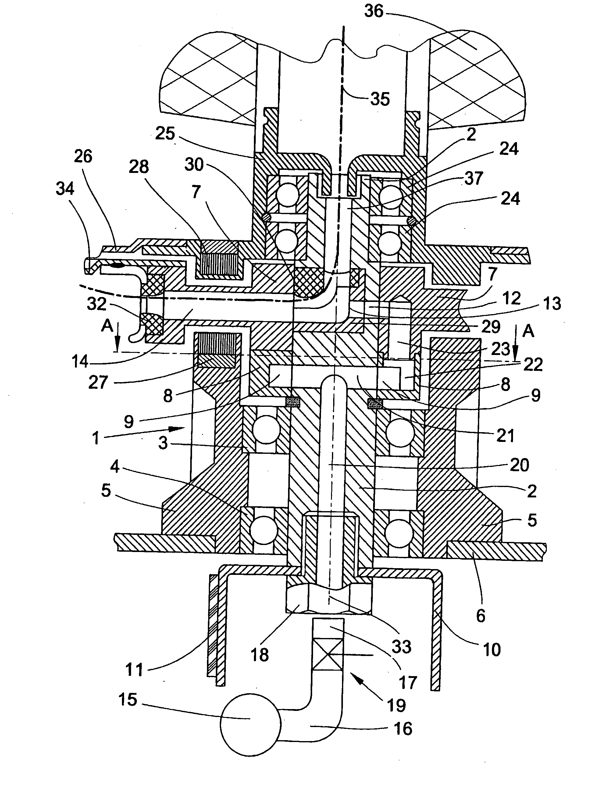
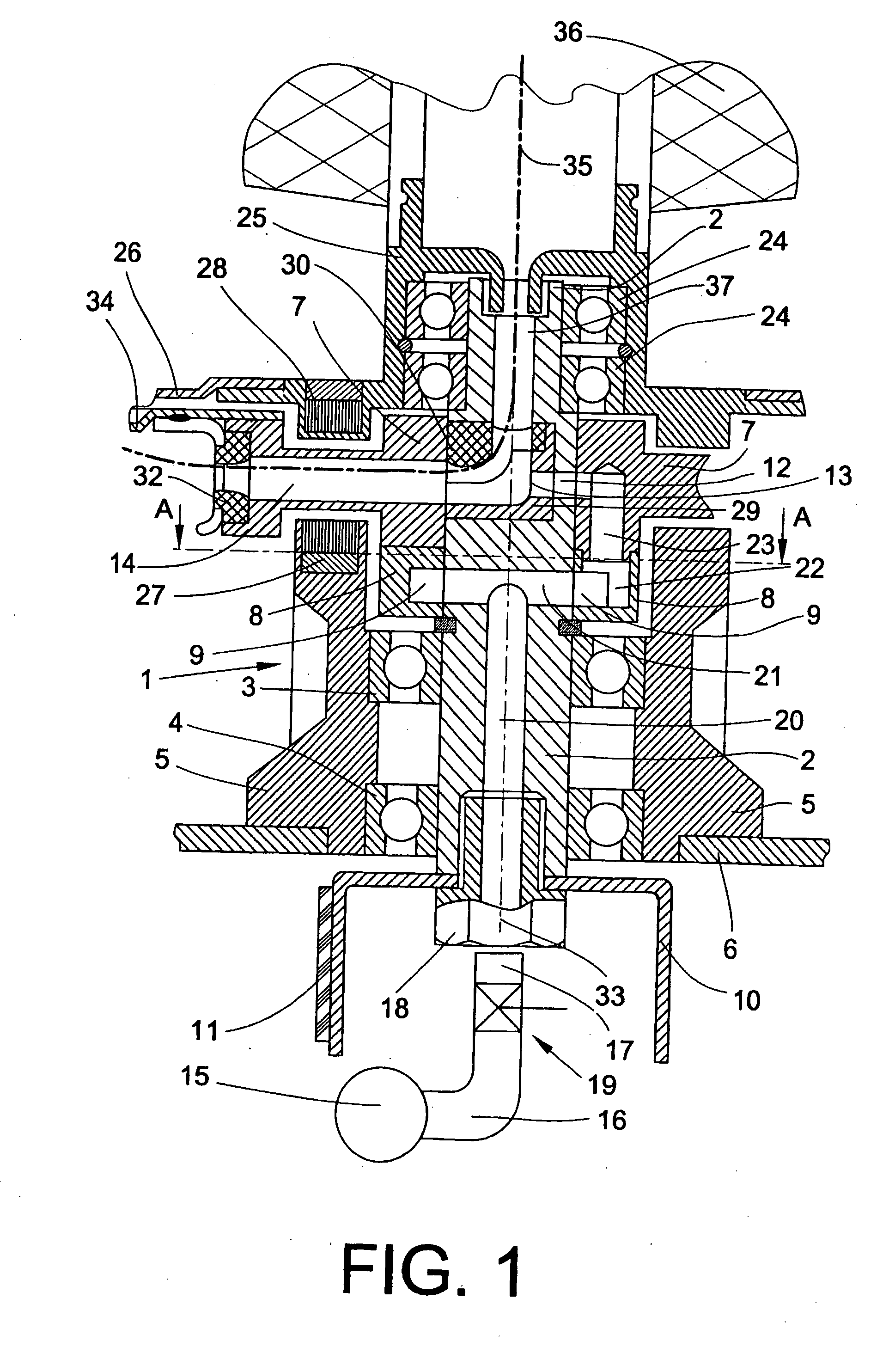
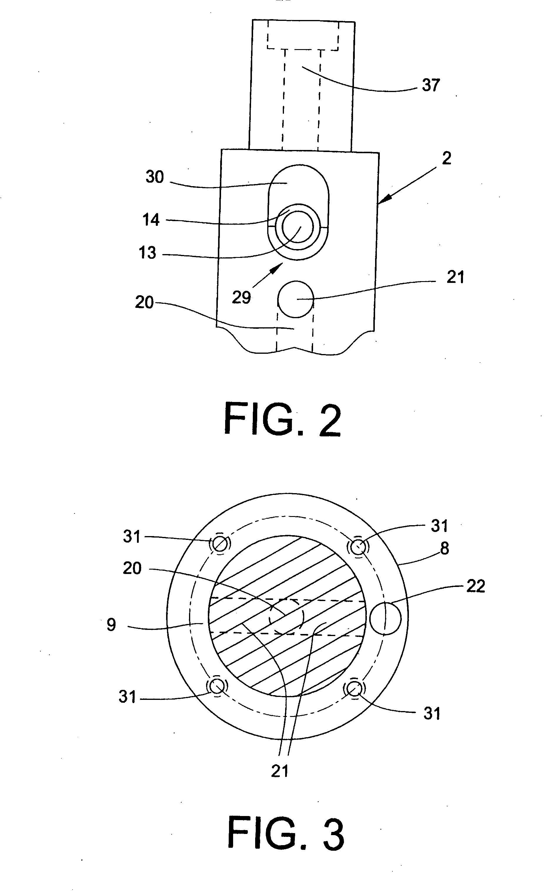
[0021]FIG. 1 shows a two-for-one twisting spindle comprising a spindle bearing 1. The spindle bolt 2 is rotatably mounted in the bearing housing 5 by means of ball bearings 3, 4. The bearing housing 5 is fastened to the spindle rail 6. The spindle bolt 2 has a thread guiding ring 7, a U-shaped annular flange 8 with an annular chamber 9 and a drive wharve 10, which can be driven by means of a tangential belt 11. The spindle bolt 2 has an injector 12, the injector mouth 13 of which is directed onto the thread guiding channel 14. The injector 12 is temporarily connected to a compressed air source 15. The air flow in the compressed air line 16 can be interrupted by means of a shut-off device 19. The tube mouth 17 of the compressed air line 16 leading from the compressed air source 15 to the spindle bolt 2 is stationarily arranged underneath the spindle bolt 2. A stationary compressed air supply unit of this type is described in detail in DE 30 12 427 C2. The compressed air line 16 ends ...


PUM

PropertyMeasurementUnit
weightaaaaaaaaaa
diameteraaaaaaaaaa
air pressureaaaaaaaaaa

Abstract

Disclosed is a two-for-one twisting spindle comprising a pneumatically actuated threading device, a spindle bolt (2) that is rotatable about the vertical rotary shaft (33) thereof, and an injector (12) which extends into a thread guiding channel (14). Said injector (12) can be temporarily connected to a compressed air source (15). The thread (35) is conveyed through the thread guiding channel (14) by means of an air flow during the threading process. The compressed air supply unit is provided with an annular chamber (9) which is mounted upstream of the injector (12) and is formed by a rigid annular flange (8) that extends around the spindle bolt (2) and is joined thereto in a fixed manner. The invention can be used in two-for-one twisters.

Description

CROSS-REFERENCE TO RELATED APPLICATIONS [0001] This application claims the benefit of German patent application 10 2004 050 180.7, filed Oct. 14, 2004, herein incorporated by reference. BACKGROUND OF THE INVENTION [0002] The invention relates to a two-for-one twisting spindle comprising a pneumatically actuated threading device and, more particularly, to such a twisting spindle comprising a spindle bolt that is rotatable about its vertically arranged rotational axis, wherein an injector opens into a thread guiding channel, the injector can be temporarily connected to a compressed air source by a compressed air supply and the thread is conveyed through the thread guiding channel by means of an air flow during the threading process. [0003] In the case of two-for-one twisting spindles, the thread is generally drawn off upwardly from the stationary supply bobbin, introduced into the upper end of a thread inlet tube, deflected downwardly and guided to the spindle rotor which it leaves th...

Claims


Application Information

Patent Timeline
Patent Type & Authority Applications(United States)
IPC IPC(8): D01H5/28
CPCD01H7/86D01H15/007D01H7/88
Inventor FINK, HEINZAPPELHANS, LUDWIG
Owner SAURER GERMANY GMBH & CO KG
Learn More