Battery Cold Plate and Chassis with Interlocking Joints

a cold plate and chassis technology, applied in the field of cold plates, can solve the problems of adding weight to an aircraft, insufficient joints between the plates, and insufficient fluid-tight bonding between the plates, so as to reduce the number of parts, save space and weight in the aircraft, and be sufficiently robust.

Pending Publication Date: 2022-08-11
TEXTRON INNOVATIONS
View PDF10 Cites 2 Cited by
  • Summary
  • Abstract
  • Description
  • Claims
  • Application Information

AI Technical Summary

Benefits of technology

[0003]In some versions, it may be desirable to provide a cooling plate to provide localized cooling to a component that generates heat as well as to support the weight of such component. For instance, in an aircraft, such a cold plate can reduce the number of parts needed to provide cooling to conserve space and weight in the aircraft. It may also be desirable to provide a cold plate that is sufficiently robust to withstand a vibratory environment, such as on an aircraft, to inhibit a cooling medium with the cold plate to leak from the cold plate to surrounding components. Accordingly, a cold plate is described herein that is configured to provide both cooling and support for a component that is sufficiently robust to inhibit a cooling medium to leak from the cold plate in a vibratory environment.

Problems solved by technology

Such joints may be insufficient for providing a fluid-tight bond between the plates to avoid loss of coolant in a vibratory environment, such as during operation of an aircraft.
The structure of such cold plates may also be inadequate for supporting the cooled component such that additional parts may be needed to support the cooled component, which may thereby add weight to an aircraft.

Method used


Image

  • Battery Cold Plate and Chassis with Interlocking Joints
  • Battery Cold Plate and Chassis with Interlocking Joints
  • Battery Cold Plate and Chassis with Interlocking Joints

Examples


Embodiment Construction

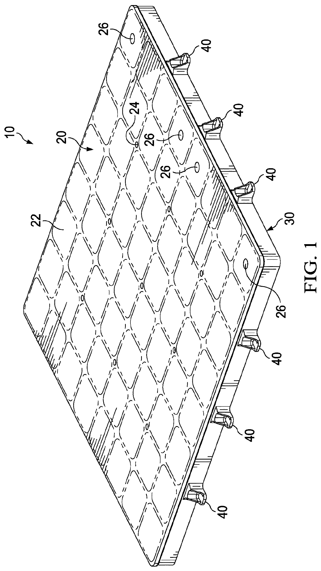
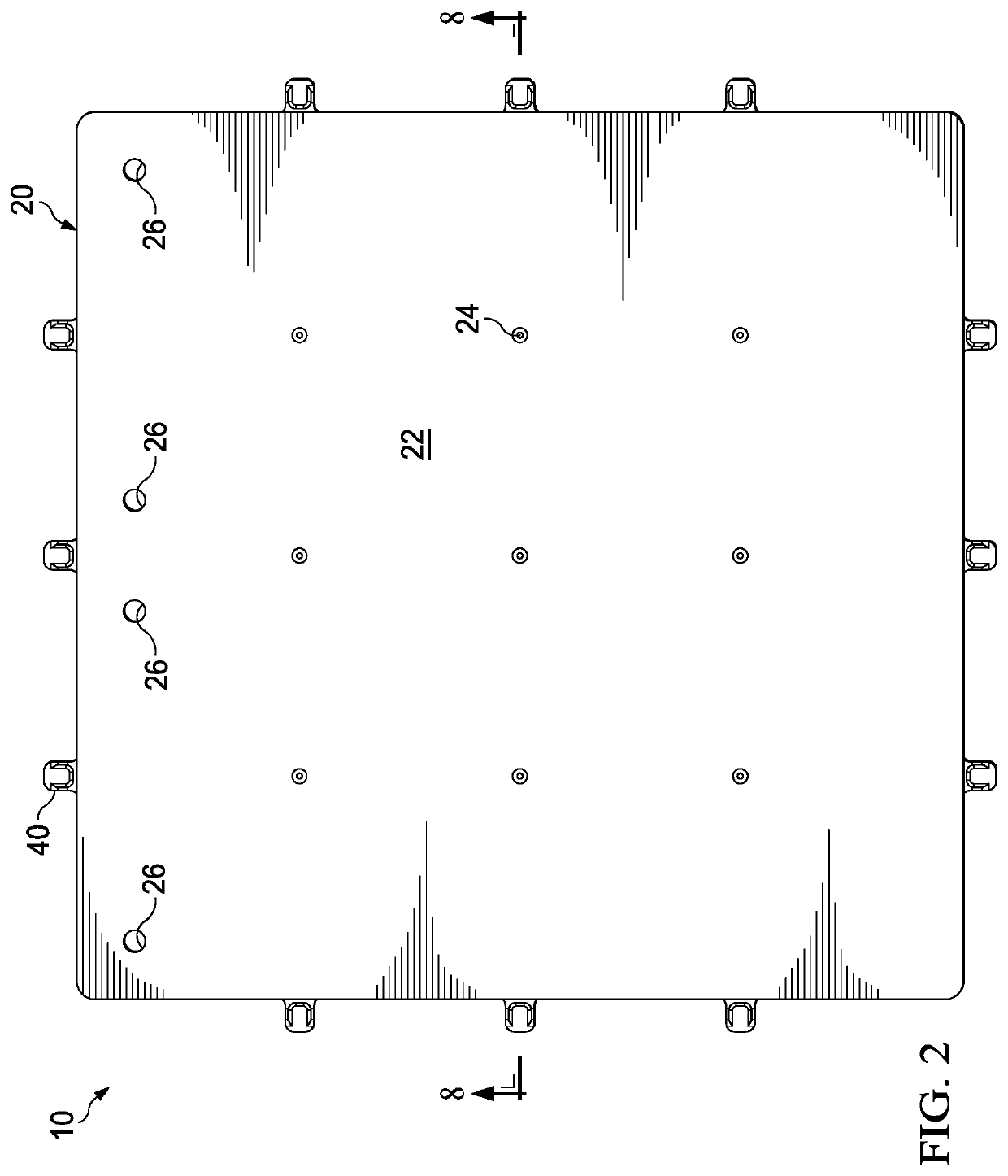
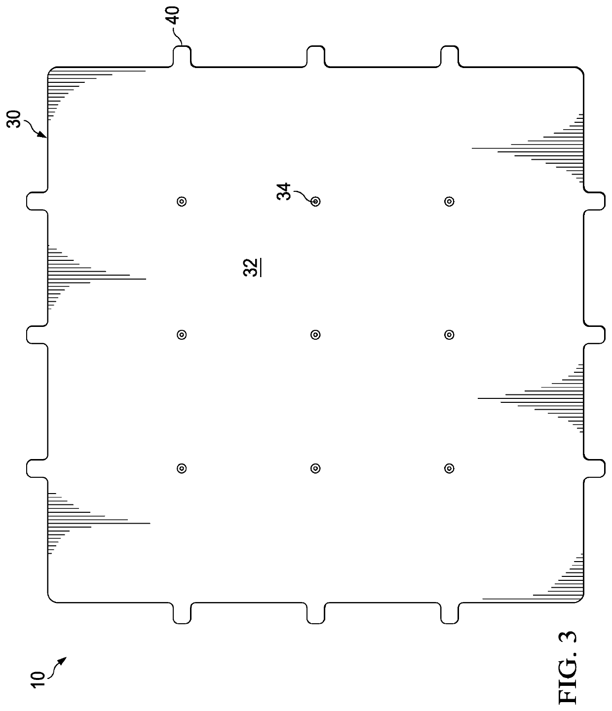
[0029]A cold plate is provided for cooling a component coupled with the cold plate. The cold plate can comprise a top plate coupled with a bottom plate to allow a cooling medium to flow between the top and bottom plates to thereby dissipate heat from the component coupled with the cold plate. The top plate can comprise a plurality of walls extending downwardly from the top plate toward bottom plate having a recess extending within each wall of the plurality of walls. The bottom plate can comprise a plurality of walls corresponding to the plurality of walls of the top plate such that the plurality of walls of the bottom plate are configured to insert within the recesses of the plurality of walls of the top plate to form an interlocking joint. Such interlocking joints can be bonded to form a fluid-tight seal to inhibit cooling medium from leaking through the interlocking joints. The plurality of walls of the top and bottom plates can further form one or more compartments for directing...


PUM

PropertyMeasurementUnit
heightaaaaaaaaaa
thicknessaaaaaaaaaa
thicknessaaaaaaaaaa

Abstract

A cold plate is couplable with a component for dissipating heat from a component. The cold plate includes a top plate coupled with a bottom plate to receive a cooling medium therebetween. The top plate includes a body and a plurality of walls extending from the body, wherein each wall of the plurality of walls includes a recess extending within the wall. The bottom plate includes a body and a plurality of walls extending from the body such that an end portion of each wall of the bottom plate is inserted within the recess of each wall of the top plate to form an interlocking joint.

Description

TECHNICAL FIELD[0001]The present disclosure is directed to in general to the field of cold plates and, more particularly, though not exclusively, to a cold plate for providing localized cooling of a component that generates heat and for supporting the weight of the component.BACKGROUND OF THE INVENTION[0002]In general, cold plates provide localized cooling for a component that generates heat, such as batteries or other electrical components, by transferring heat from the component to a cooling medium within the cold plate. In some versions, cold plates further use a series of thermally conductive metallic tubes, an open manifold, and / or internal cooling fins as a heat sink to aid in dissipating the heat. Cold plates typically include two thermally conductive metallic plates joined together in parallel to allow a coolant, such as air and / or liquid, to flow between them as the cooling medium. Many ways have been developed to join these two plates together such as brazing, soldering, f...

Claims


Application Information

Patent Timeline
Patent Type & Authority Applications(United States)
IPC IPC(8): H01M10/6554H01M10/6556H01M10/613H01M10/625F28F3/12
CPCH01M10/6554H01M10/6556H01M10/613F28D2021/0019F28F3/12H01M2220/20H01M10/625F28D2021/0029F28D1/03
Inventor AMANTE, WILLIAM A.CLOUD, JEFFREY B.
Owner TEXTRON INNOVATIONS
Why Eureka
Try Eureka