Vehicle mounted compressed air distribution system

a compressed air distribution system and vehicle mount technology, applied in the direction of fluid pressure control, instruments, packaged goods, etc., can solve the problems of occupying space, adding weight, and requiring constant maintenance, and affecting the fire truck in which space and weight are at a premium, so as to achieve more reliable and self-illuminating, the effect of greater flexibility

Inactive Publication Date: 2006-04-20
AMERICAN COMPRESSED AIR SYST & CONSULTING
View PDF13 Cites 3 Cited by
  • Summary
  • Abstract
  • Description
  • Claims
  • Application Information

AI Technical Summary

Benefits of technology

[0005] In this way, the vessel pressures may be monitored without pressurized lines running between each vessel and the control panel. Also, the mechanical liquid filled dial-type gauges typically used are replaced with digital numeric read-outs which are more reliable and self-illuminating. Thereby, all of the prior art hoses running to and from the control panel are replaced by a wiring harness which is much more compact and reliable. Replacing the pressurized air hoses with electrical wiring also allows greater flexibility for the location of the compressed air vessels on the truck. The system is powered by the 12-volt electrical supply already present on the truck.
[0007] It is therefore an object of the present invention to provide a vehicle mounted air distribution system which saves space and weight. A further object of the present invention is to create a compact air distribution system for a vehicle which is extremely reliable and easy to maintain. Other objects and advantages of the invention will become apparent to those of skill in the art from the following drawings and description of the preferred embodiment.

Problems solved by technology

The problem with this arrangement is that each supply cylinder has a separate live air hose running to a gauge on the control panel and then lines to the air station.
This system uses a great deal of air hose plumbing which takes up space, adds weight, and requires constant maintenance since leaks may develop in the myriad of air lines which travel to and from the supply cylinders to the control panel and then from the control panel to the fill station.
This is detrimental to the fire truck in which space and weight are at a premium.

Method used


Image

  • Vehicle mounted compressed air distribution system
  • Vehicle mounted compressed air distribution system
  • Vehicle mounted compressed air distribution system

Examples


Embodiment Construction

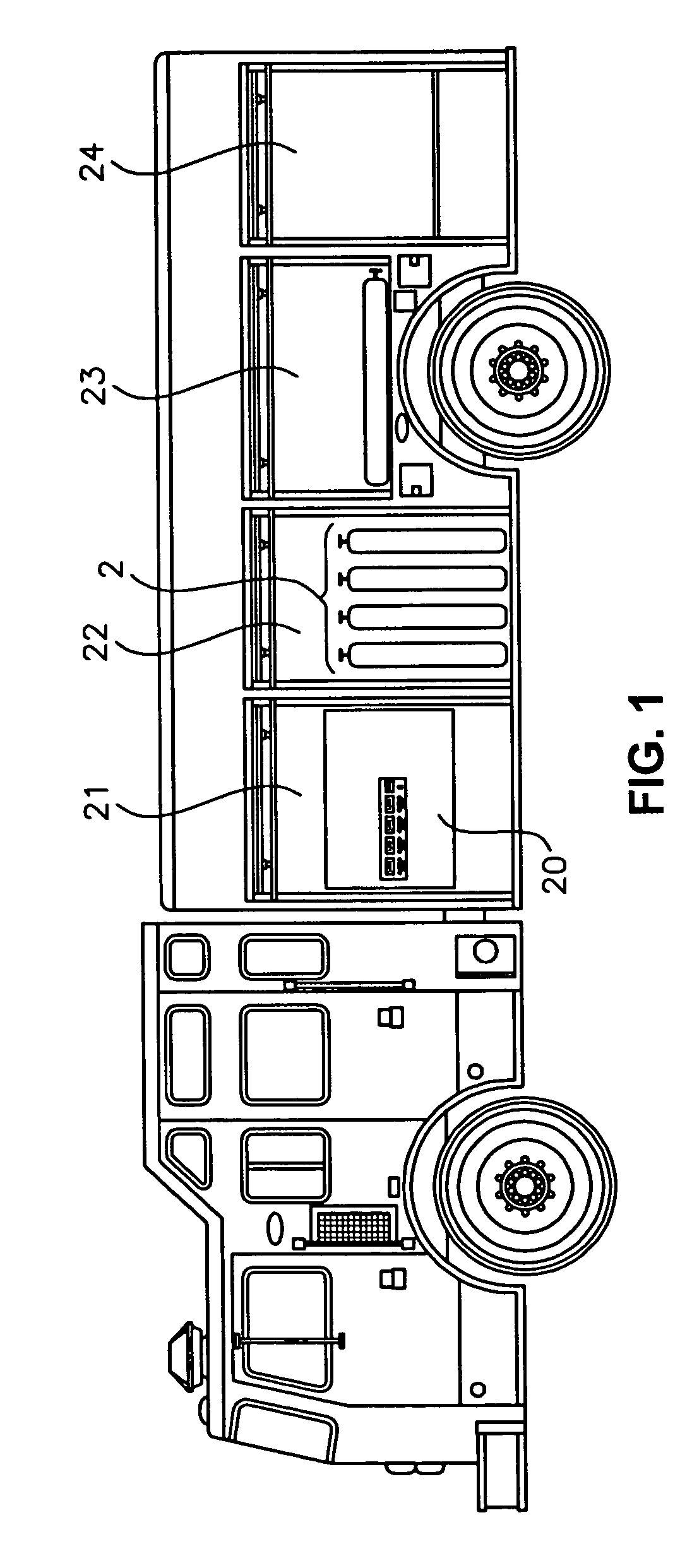
[0011] Referring now to FIG. 1, a fire truck that utilizes the air distribution of the present invention is shown. The fire truck includes compartments 21, 22, 23 and 24 which may be used for storage of various items such as compressed air cylinders 2. Compartment 21 in this drawing functions as an air access station which includes control panel 20 that has monitoring and control means for distributing compressed air. Compressed air is typically used by fire trucks to refill rescue personnel backpack-mounted air bottles, to power hand tools, and for other purposes. The compressed air for distribution, as shown in this embodiment, is stored in a bank of cylinders 2 which occupy compartment 22 remote from the compressed air access station of compartment 21.

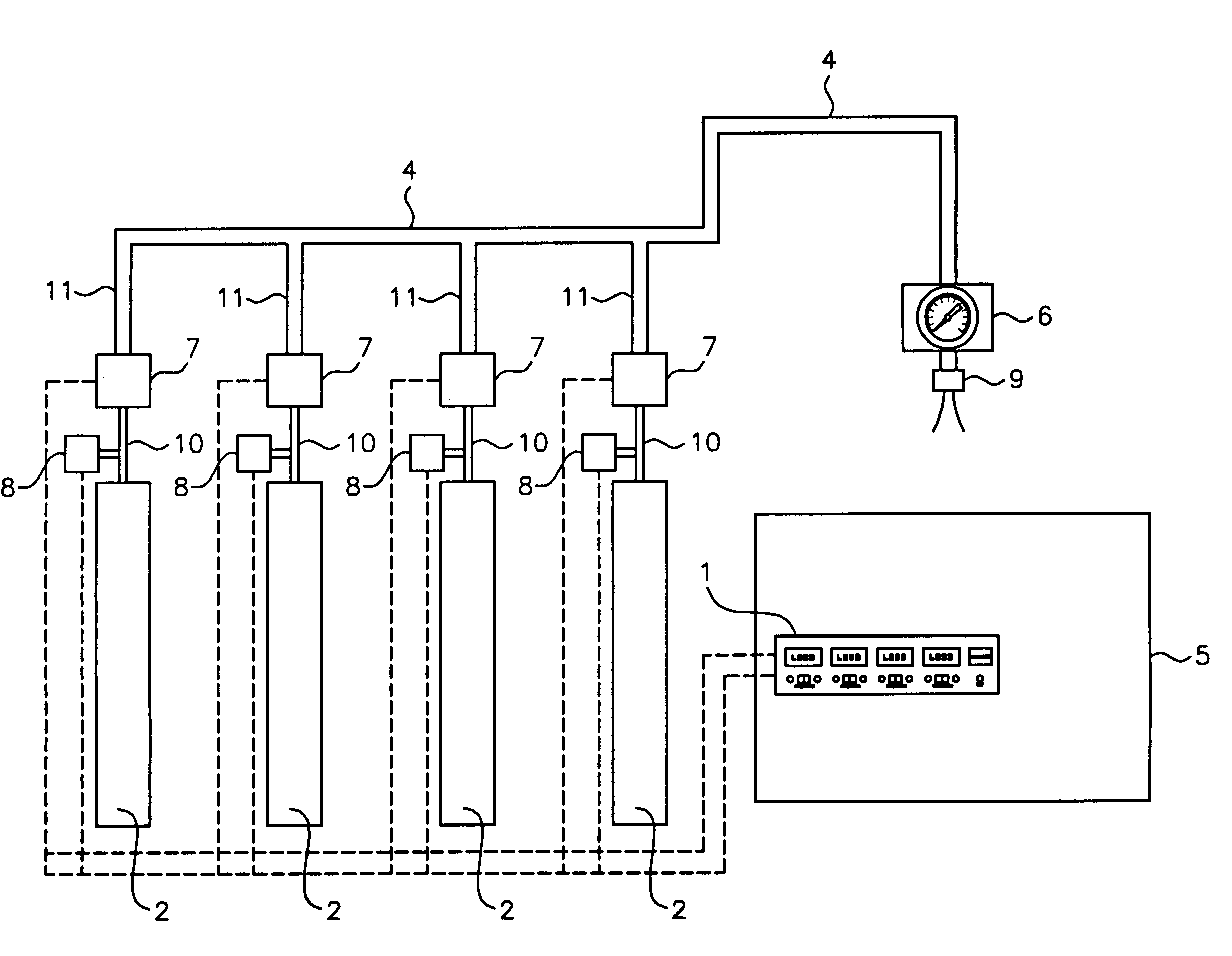
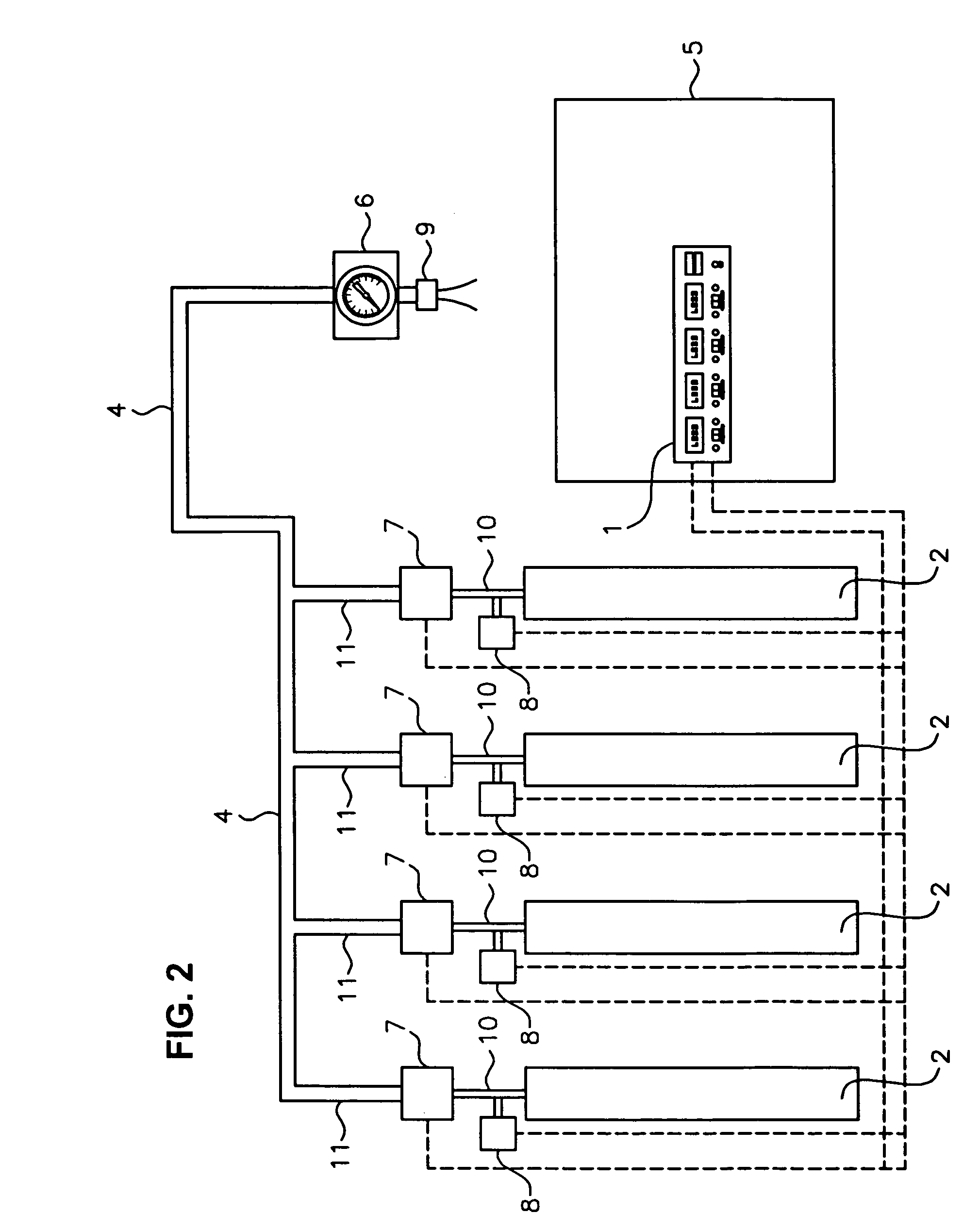
[0012] Referring now to FIG. 2, this diagram depicts the compressed air distribution system of the invention in which compressed air from cylinders 2 is fed to fill port 9 monitored and controlled by control panel 5. Each air cylin...


PUM

PropertyMeasurementUnit
pressureaaaaaaaaaa
Pressureaaaaaaaaaa
weightaaaaaaaaaa

Abstract

A pressurized gas system controls a gas flow from one or more gas pressure storage vessels by means of an electronically controlled electro-mechanical shut-off valve located in close proximity to each of the vessels. The shut-off valves are electrically wired to actuation switches on the control panel. Pressure transducers mounted on each vessel provide a signal output which is electrically connected to a digital numeric display located on the control panel so that the pressure of each vessel can be monitored. Gas flow from the vessels is controlled by means of the electric shut-off valves operated from the control panel. A pressure regulator at the air access station controls the final output pressure delivered to the tool or personnel air bottle. Thus, the vessel pressures may be monitored without pressurized lines running between each vessel and the control panel and the mechanical liquid filled dial-type gauges typically used are replaced with digital numeric read-outs which are more reliable and self-illuminating.

Description

FIELD OF THE INVENTION [0001] The present invention relates to mobile compressed air systems, more specifically for compressed air monitoring and delivery systems used on rescue type vehicles such as fire trucks. BACKGROUND OF THE INVENTION [0002] Rescue type vehicles such as fire trucks often carry a supply of compressed air which is contained in a bank of pressurized vessels or cylinders. The compressed air cylinders are housed on the vehicle in a remote storage compartment. Pressurized lines run from each cylinder to a panel of pressure gauges and controls usually located on the side of the truck. The cylinders are plumbed in parallel and have feed lines which run to a compressed air station on the truck adjacent the control panel. Rescue personnel carry backpack mounted air bottles which supply their individual personal breathing apparatus. As these air bottles become depleted, they are refilled at the truck compressed air station. The compressed air is also used to power hand t...

Claims


Application Information

Patent Timeline
Patent Type & Authority Applications(United States)
IPC IPC(8): G05D11/00
CPCF17C2227/043G05D16/2046Y10T137/2668Y10T137/267Y10T137/2673
Inventor MUSSELMAN, BRETT A.KUDER, CURTIS G.
Owner AMERICAN COMPRESSED AIR SYST & CONSULTING
Why Eureka
Try Eureka