

Gas turbine engine with pylon mounted accessory drive
a technology of accessory drive and gas turbine engine, which is applied in the direction of machines/engines, sustainable transportation, mechanical equipment, etc., can solve the problems of nacelle design providing less than optimal performance at cruise conditions, occupying a relatively significant amount of space within the engine core nacelle, etc., to facilitate direct drive, save weight and space, and reduce the temperature of the operating environment.
- Summary
- Abstract
- Description
- Claims
- Application Information
AI Technical Summary
Benefits of technology
Problems solved by technology
Method used
Image

Examples
Embodiment Construction
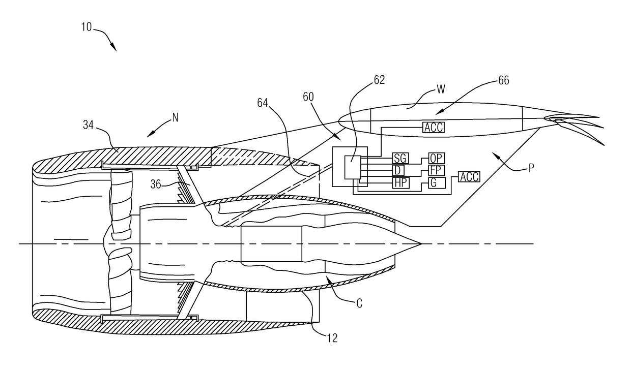
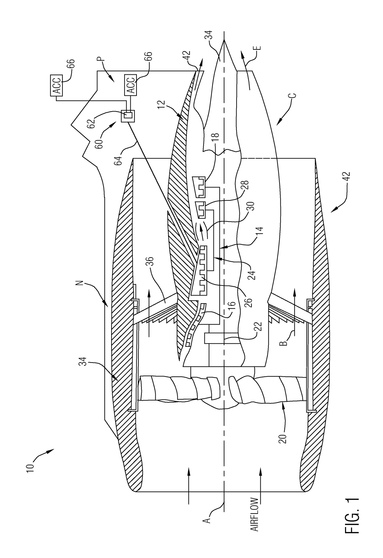
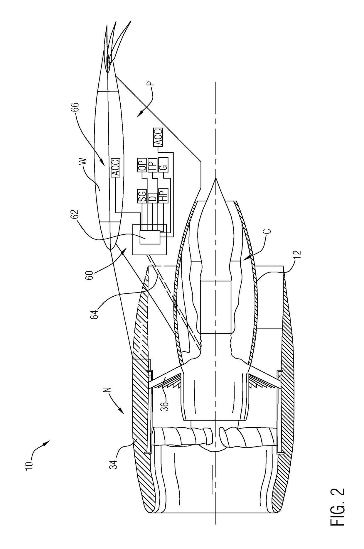
[0011]FIG. 1 illustrates a general partial fragmentary schematic view of a gas turbine engine 10 suspended from an engine pylon P within an engine nacelle assembly N as is typical of an aircraft designed for subsonic operation. The engine pylon P or other support structure is typically mounted to an aircraft wing W (FIG. 2), however, the engine pylon P may alternatively extend from other aircraft structure such as an aircraft empennage.
[0012]The turbofan engine 10 includes a core engine C within a core nacelle 12 that houses a low spool 14 and high spool 24. The low spool 14 includes a low pressure compressor 16 and low pressure turbine 18. The low spool 14 may drive a fan section 20 through a gear train 22. The high spool 24 includes a high pressure compressor 26 and high pressure turbine 28. A combustor 30 is arranged between the high pressure compressor 26 and high pressure turbine 28. The low and high spools 14, 24 rotate about an engine axis of rotation A.
[0013]The engine 10 in...
PUM
 Abstract
Description
Claims
Application Information