Shield assembly with gaskets

Active Publication Date: 2008-02-28
HONG FU JIN PRECISION IND (SHENZHEN) CO LTD +1
View PDF4 Cites 37 Cited by
  • Summary
  • Abstract
  • Description
  • Claims
  • Application Information

AI Technical Summary

Benefits of technology

[0008]In one aspect of the embodiment, a shielding assembly mounted on a circuit board includes a cage, a shielding plate, a supporting frame, and a gasket. The cage includes an outer surface, a front end portion, a rear end portion opposite to the front end portion, a plurality of stop portions, and a plurality of clips. The stop portions and the clips respectively protrude from the outer surface. The shielding plate is mounted to a front portion of the cage, and includes a main portion, a plurality of tabs pro

Problems solved by technology

However, there are gaps between the front panel of the device and the cage, between the cage and the PCB, and between the front end portion and the module, thereby the cage does not effectively shield the module from external elec

Method used


Image

  • Shield assembly with gaskets
  • Shield assembly with gaskets
  • Shield assembly with gaskets

Examples


Example

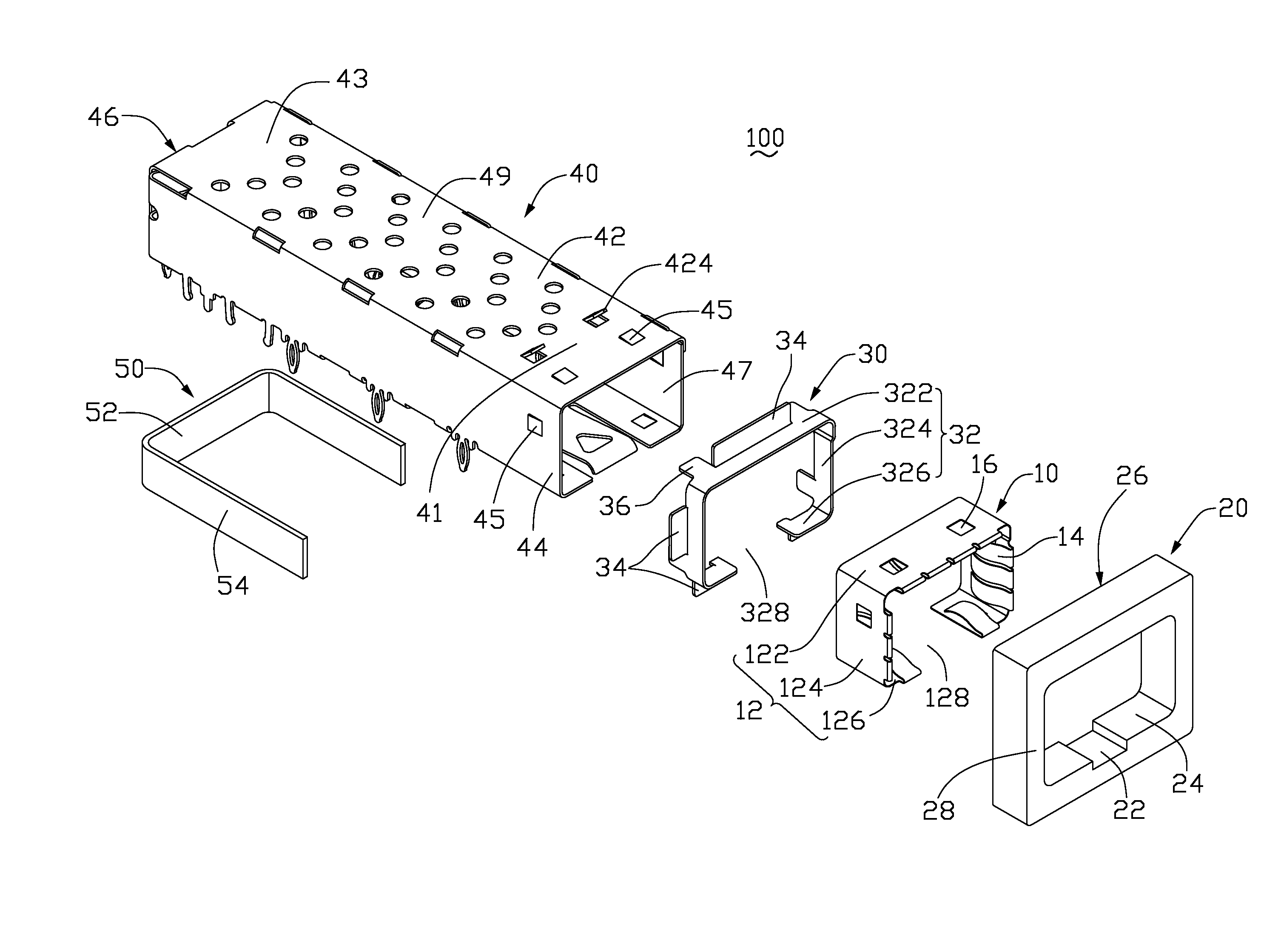
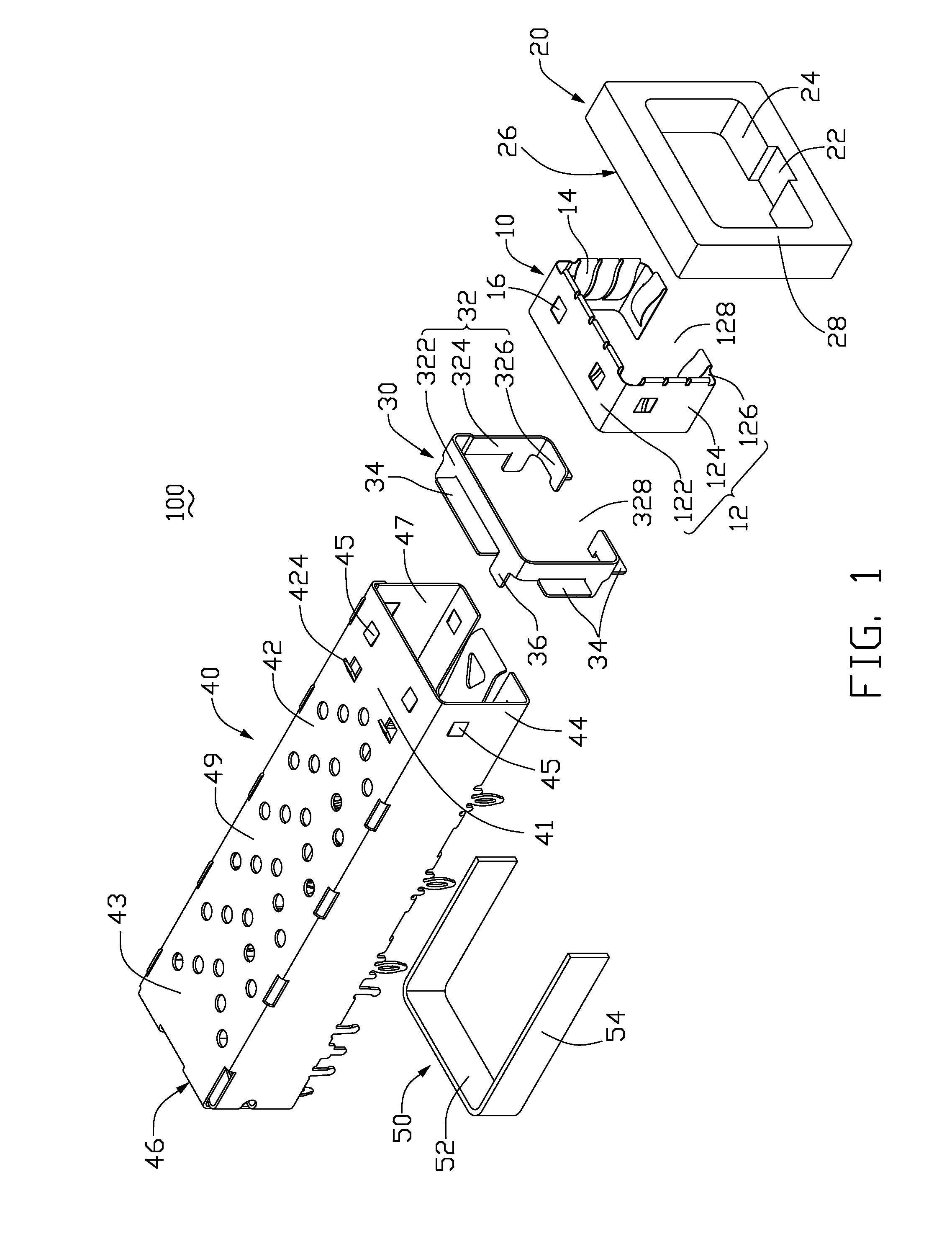
[0016]Referring to FIGS. 1 and 4, a shielding assembly 100 of an exemplary embodiment of the present invention is shown. The shielding assembly 100 is mounted on a circuit board 200. The shielding assembly 100 includes a shielding plate 10, a first gasket 20, a supporting frame 30, a cage 40, and a second gasket 50.

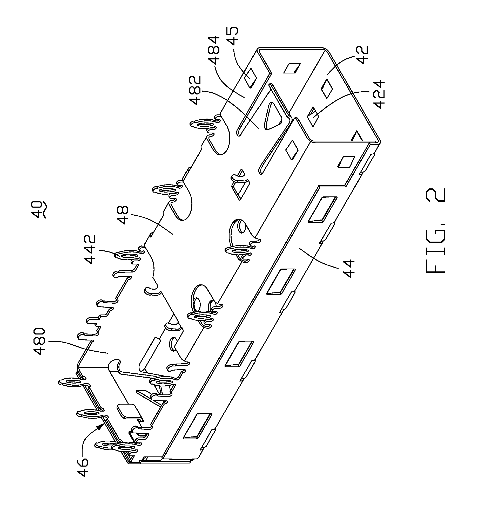
[0017]Referring also to FIG. 2, the cage 40 is configured for housing a module (not shown), and shielding the module from external electromagnetic waves, as well as containing electromagnetic waves emanating from the module. The cage 40 is substantially rectangular and it will be understood that other configurations may be utilized. The cage 40 is constructed from sheet metal, and includes a top wall 42, a pair of parallel sidewalls 44, a back wall 46 perpendicularly connected to the top wall 42 and the sidewalls 44, a bottom wall 48 parallel to the top wall 42, a front end portion 41, and rear end portion 43 opposite to the front end portion 41. The top wall 42, the side...


PUM


Abstract

A shielding assembly includes a cage (40), a shielding plate (10), and a gasket (50). The cage includes a front end portion (41), a rear end portion (43) opposite to the front end portion, a plurality of clips (45) protruding from the front end portion, a pair of sidewalls (44), and a back wall (46). The shielding plate attached to the front end portion of the cage, includes a main portion (12), a plurality of resilient tabs (14) projecting from an inner surface of the main portion, and a plurality of through hatches (16) in the main portion for receiving the clips. The gasket is attached to the rear end portion and abuts against outer surfaces (49) of the sidewalls and the back wall.

Description

BACKGROUND OF THE INVENTION[0001]1. Field of the Invention[0002]The present invention relates to a shield assembly for shielding electromagnetic interference (EMI), and specifically to a shield assembly with gaskets configured for shielding transceiver module from EMI.[0003]2. Description of Related Art[0004]Transceiver modules provide bi-directional transmission of data between an electrical interface and an optical data link. The module receives electrical signals and converts them into optical signals that are then transmitted over the optical data link. The module also receives optical signals, converts them into electrical signals, and transmits the electrical signals to the electrical interface.[0005]Conventionally, the module connected to a metal cage is mounted on a printed circuit board (PCB) of a host computer, an input / output system, a peripheral device, or a switch. The metal cage functions to dissipate electrostatic buildup, and serves as an electromagnetic shield. The ...

Claims


Application Information

Patent Timeline
IPC IPC(8): H05K9/00
CPCH05K9/0058
Inventor CHEN, JIAN-PINGWANG, WAN-CHENG
Owner HONG FU JIN PRECISION IND (SHENZHEN) CO LTD
Why Eureka
Try Eureka