Backlight unit and liquid crystal display device

a liquid crystal display device and backlight technology, applied in mechanical devices, lighting and heating apparatus, instruments, etc., can solve the problems of uneven brightness, waste of transmitted illumination light, uneven brightness, etc., and achieve the effect of preventing the occurrence of uneven brightness

Inactive Publication Date: 2008-02-28
SATURN LICENSING LLC
View PDF11 Cites 60 Cited by
  • Summary
  • Abstract
  • Description
  • Claims
  • Application Information

AI Technical Summary

Benefits of technology

[0019]Accordingly, since the reflective portion is provided at the side surface of the light guide plate to which the light-source substrate having the light-emitting elements is attached, the incidence angle of illumination light incident on the light guide plate near the light source can be made equal to or above the critical angle. This allows the illumination light to undergo total reflection, thereby preventing the occurrence of unevenness in brightness.

Problems solved by technology

This results in unfavorable transmission of the illumination light through the light guide plate 103.
This unfavorably causes the illumination light to be transmitted through the light guide plate 103, which may cause unevenness in brightness, such as bright spots and bright lines that are displayed brighter than the surrounding areas.
For this reason, the transmitted illumination light is wasted and not utilized efficiently.

Method used


Image

  • Backlight unit and liquid crystal display device
  • Backlight unit and liquid crystal display device
  • Backlight unit and liquid crystal display device

Examples


Embodiment Construction

[0036]A backlight unit and a liquid crystal display device according to embodiments of the present invention will be described below with reference to the drawings.

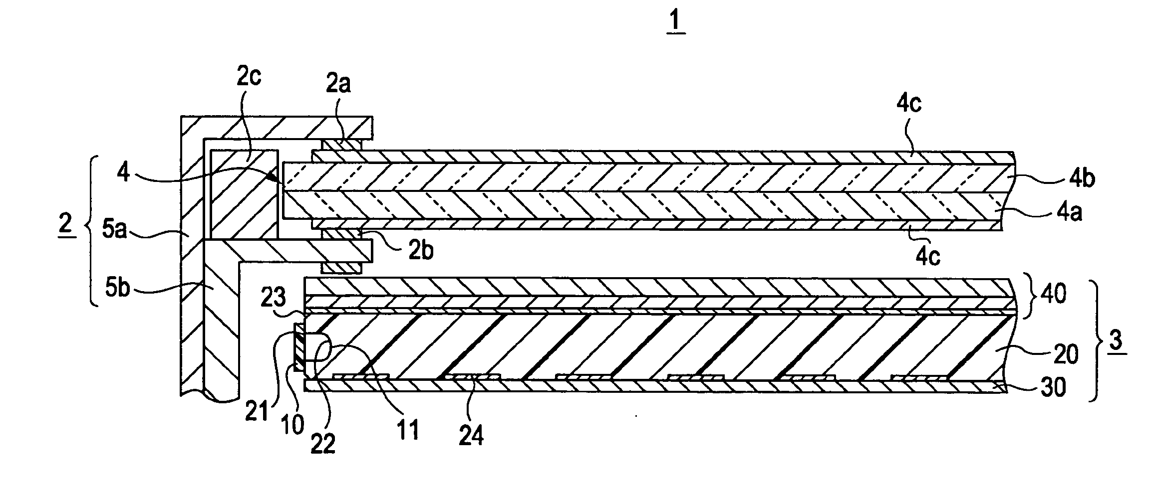
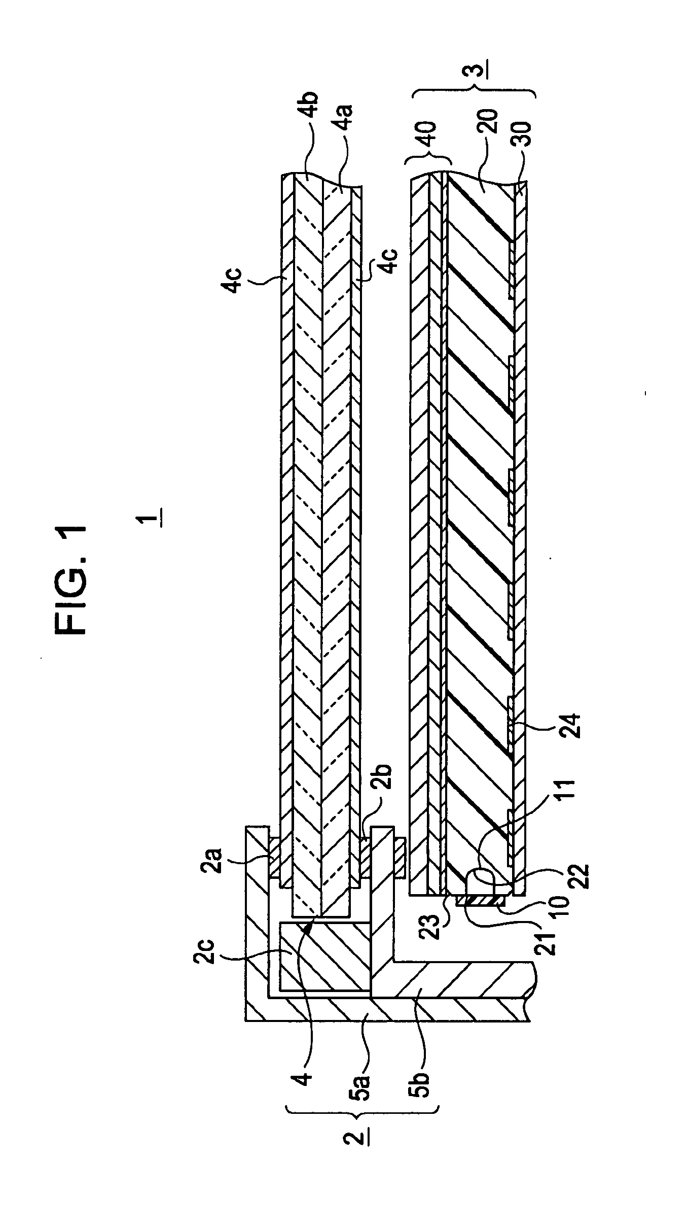
[0037]A liquid crystal display device 1 according to an embodiment of the present invention is used in, for example, a display panel for a television receiver. Referring to FIG. 1, the liquid crystal display device 1 includes a liquid crystal panel unit 2 having a transmissive liquid crystal panel 4, and a backlight unit 3 according to an embodiment of the present invention. The backlight unit 3 is combined with the liquid crystal panel unit 2 at a rear side thereof and emits illumination light to the liquid crystal panel unit 2.

[0038]The liquid crystal panel unit 2 receiving illumination light of the backlight unit 3 from the rear includes the liquid crystal panel 4 having a substantially rectangular shape, and a front frame member 5a and a rear frame member 5b that support the liquid crystal panel 4.

[0039]Referring to F...


PUM

PropertyMeasurementUnit
critical angleaaaaaaaaaa
refractive indexaaaaaaaaaa

Abstract

A backlight unit includes a light-source substrate having mounted thereon a plurality of light-emitting elements emitting illumination light; a light guide plate having a side surface with the light-source substrate attached thereto so as to receive the illumination light from the light-emitting elements, the light guide plate also having a first surface extending substantially perpendicular to the side surface, and a second surface; a reflective sheet attached to the first surface and reflecting the illumination light towards the second surface; and an optical sheet layer attached to the second surface and including a plurality of stacked optical sheets. The side surface has a reflective portion that reflects at least a part of the illumination light. The at least a part of the illumination light to be reflected at the reflective portion is incident on the reflective portion at an incidence angle equal to or above a critical angle.

Description

CROSS REFERENCES TO RELATED APPLICATIONS[0001]The present invention contains subject matter related to Japanese Patent Application JP 2006-227061 filed in the Japanese Patent Office on Aug. 23, 2006, the entire contents of which are incorporated herein by reference.BACKGROUND OF THE INVENTION[0002]1. Field of the Invention[0003]The present invention relates to backlight units that illuminate transmissive liquid crystal panels and to liquid crystal display devices equipped with such backlight units.[0004]2. Description of the Related Art[0005]Liquid crystal display devices optically display, for example, predetermined images by applying voltage to liquid crystal sealed between two transparent substrates. In detail, the application of voltage causes the orientation of the liquid crystal molecules to change, thereby changing the light transmittance. A liquid crystal display device is equipped with a backlight unit that illuminates a transmissive liquid crystal panel included in the dev...

Claims


Application Information

Patent Timeline
Patent Type & Authority Applications(United States)
IPC IPC(8): G02F1/13357F21V7/04F21V8/00
CPCG02B6/0055G02B6/0021
Inventor KUBOTA, EIGO
Owner SATURN LICENSING LLC
Why Eureka
Try Eureka