Reference signal multiplexing and resource allocation

a reference signal and multiplexing technology, applied in multiplex communication, transmission path division, wireless commuication services, etc., can solve the problems of short sequence length of each reference signal, inability to exploit merit, and decrease in the number of cazac sequences that can be secured, so as to reduce the restriction on the number of reference signal sequences

Active Publication Date: 2008-02-28
NEC CORP
View PDF4 Cites 70 Cited by
  • Summary
  • Abstract
  • Description
  • Claims
  • Application Information

AI Technical Summary

Benefits of technology

[0022]As described above, according to the present invention, reference signals may be frequency-multiplexed and/or time-multiplexed depending on the usage purpose and importance of the reference signals, whereby a reduction can be achieved in the number of reference signals that are multiplexed by distributed FDM at the

Problems solved by technology

However, the reference-signal bandwidth required by each user equipment is not always the same as that required by another user equipment, and suitable transmission bandwidths differ depending on what purpose a reference signal is used for (such as for modulation/detection of a data signal, for modulation/detection of a L1/L2 control signal, or for CQI measurement).
However, distributed FDM has a demerit that the number of CAZAC sequences that can be secured decreases as the number of reference signals that are multiplexed in a certain frequency band increases.
Howev

Method used


Image

  • Reference signal multiplexing and resource allocation
  • Reference signal multiplexing and resource allocation
  • Reference signal multiplexing and resource allocation

Examples


first exemplary embodiment

1. First Exemplary Embodiment

1.1) Resource Allocation

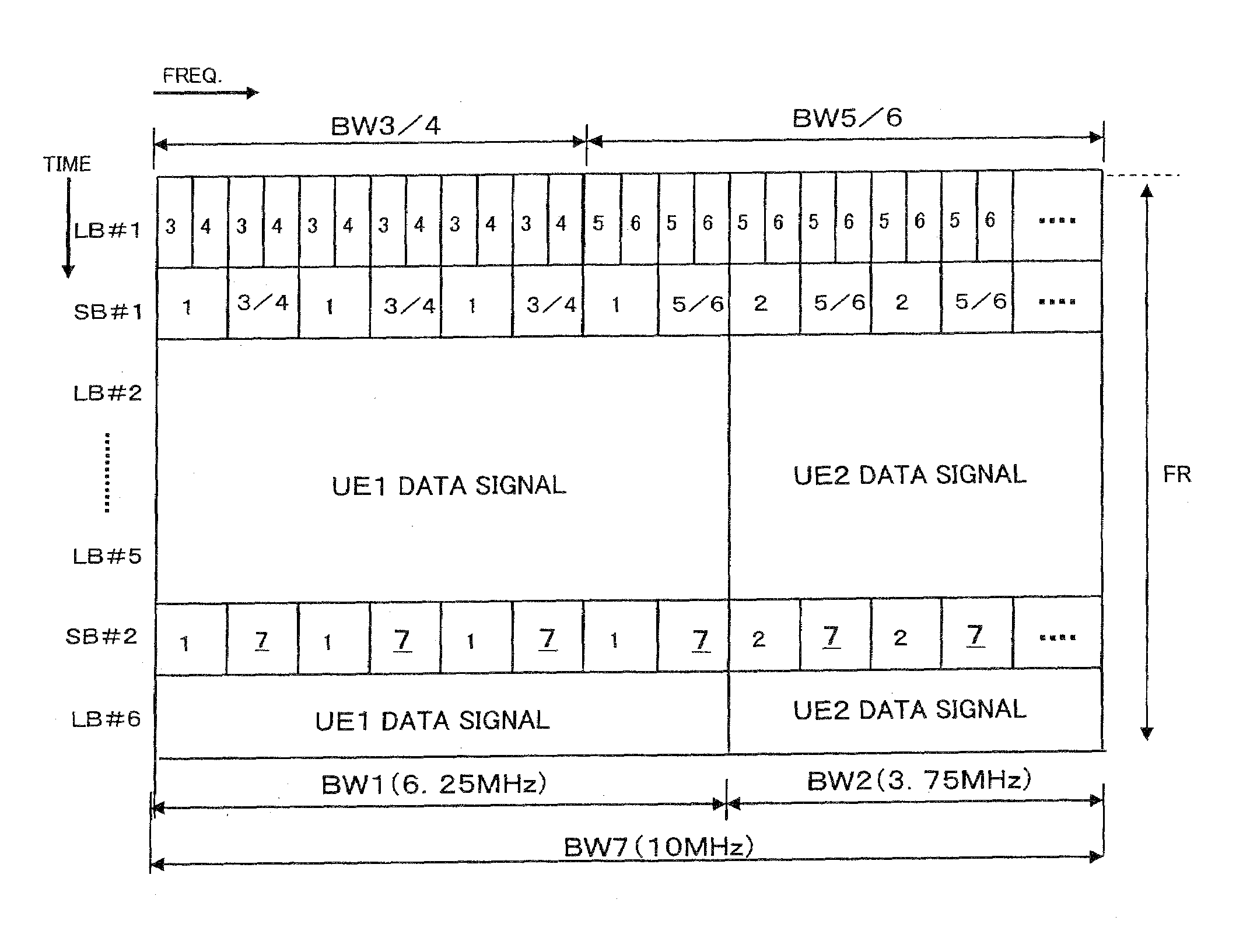
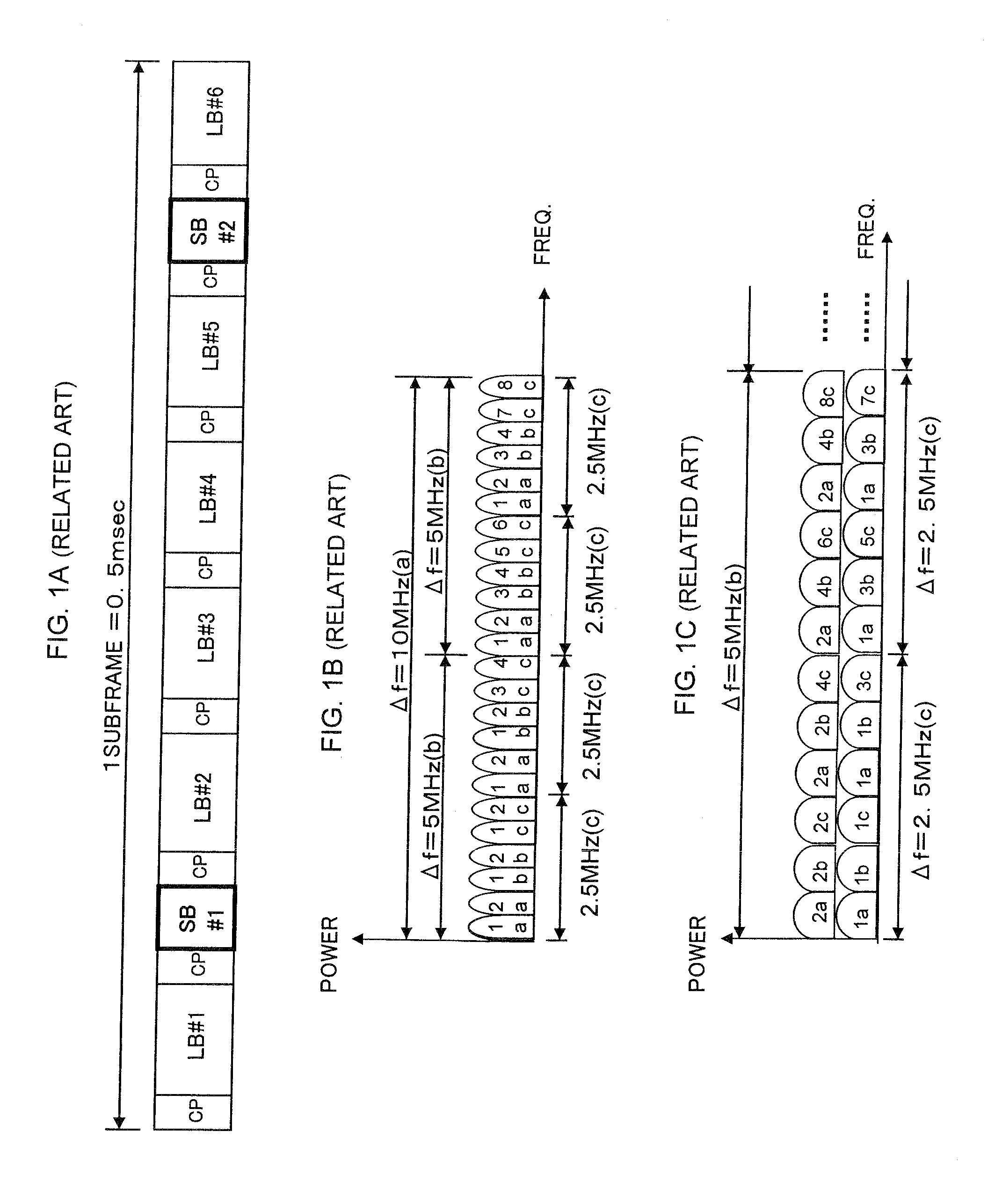
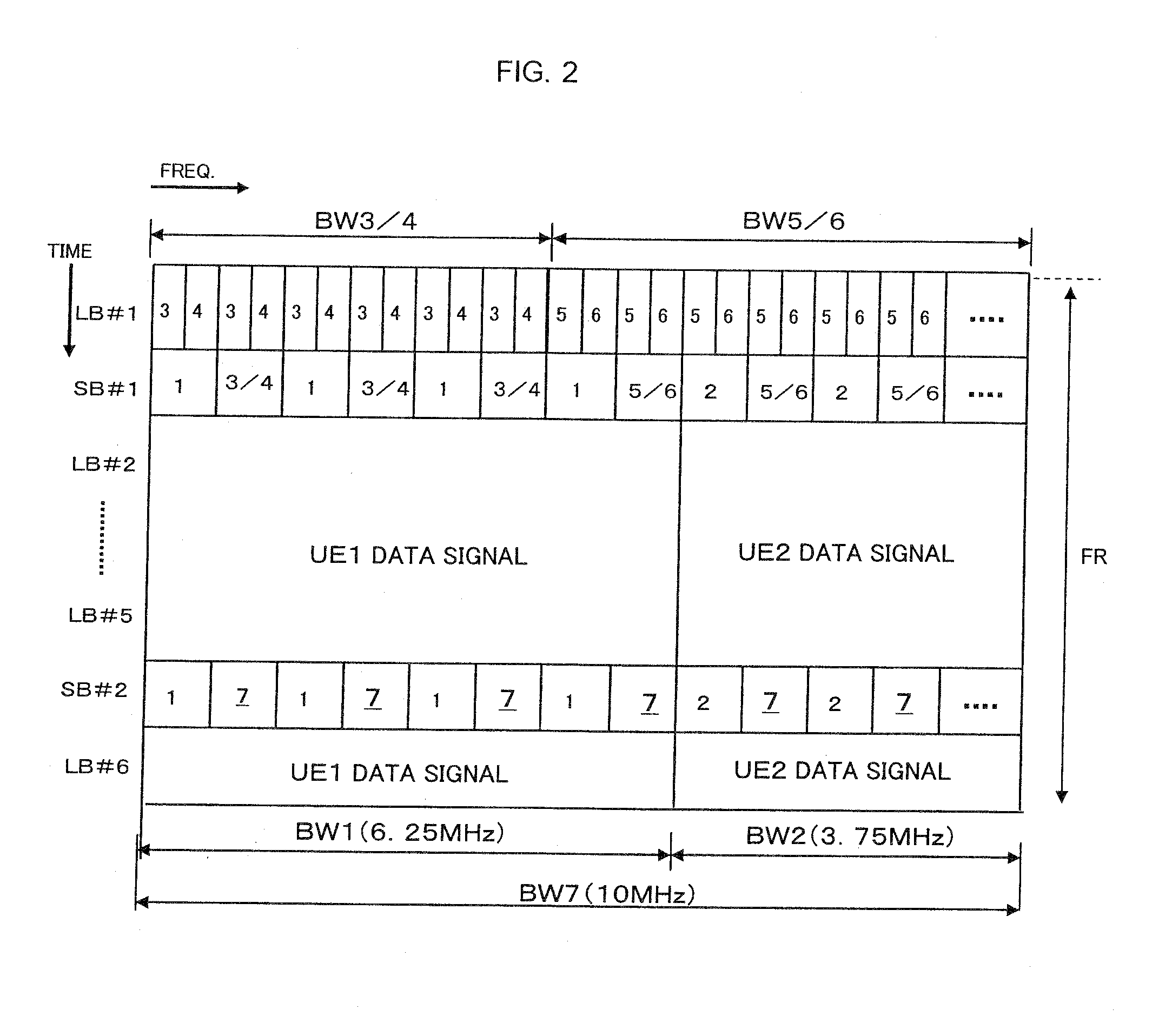
[0038]FIG. 2 is a diagram schematically showing an example of a method for multiplexing reference signals according to a first exemplary embodiment of the present invention. In this example, it is assumed that the frame structure shown in FIG. 1A is used, in which one frame (sub-frame) includes long blocks LB#1 to LB#6, short blocks SB#1 and SB#2, and cyclic prefixes (CP), with the short block SB#1 being inserted between the long blocks LB#1 and LB#2, and the short block SB#2 being inserted between the long blocks LB#5 and LB#6. In addition, it is assumed that L1 / L2 control signals are allocated the long block LB#1, that reference signals (also referred to as pilot signals) are allocated the short blocks SB#1 and SB#2, and that data signals are allocated the long blocks LB#2 to LB#6. A time interval between the short blocks SB#1 and SB#2, which reference signals are allocated, is set so that fading variance in each channel during ...

first example

[0057]It is assumed that demodulation / detection reference signals are multiplexed as described above in the section 1.2. In this state, for example, if the mobile station UE7 makes an entry for channel-dependent scheduling with its CQI estimation range set as a bandwidth BW7=10 MHz, then a reference signal for estimation of the channel quality of the mobile station UE7 should be allocated a short block.

[0058]In this case, first, it is checked whether or not an unoccupied frequency resource is present in the short block SB#2, which is subsequent to the short block SB#1. This is because the possibility of the presence of an unoccupied frequency resource applying to the above-described item (1), “a frequency resource that is not and will not be allocated for a demodulation / detection reference signal,” or an unoccupied frequency resource applying to the above-described item (2), “a frequency resource that can be allocated for a demodulation / detection reference signal and is not currentl...

second example

[0060]For example, it is assumed that the bandwidth BW7, which is the CQI estimation range for the mobile station UE7, is 6.25 MHz, the same as the frequency bandwidth BW1 for the mobile station UE1. If an unoccupied frequency resource as required is not present in the short block SB#2, then it is checked whether or not an unoccupied frequency resource is present in the short block SB#1. Although the whole short block SB#1 is occupied by the reference signals for demodulation / detection of data and control signals, the transmission bandwidth BW1 of the reference signal for demodulation / detection of the data signal matches with the transmission bandwidth BW7 required by the mobile station UE7, and the maximum number of signals that can be multiplexed by CDM in the short block SB#1 is not smaller than two. This fact meets the above-described condition A. Accordingly, a CQI estimation reference signal of the mobile station UE7 is allocated a frequency resource by being multiplexed by CD...


PUM


Abstract

A reference signal of a user equipment to which a resource (LB#1) is allocated for a L1/L2 control signal, is allocated a resource (SB#1) that is closer on the time axis to the resource (LB#1), which the L1/L2 control signal is allocated, within the same frequency band as the L1/L2 control signal. A reference signal for CQI estimation, independent of a data signal and a L1/L2 control signal, is allocated a resource with which at least one of a reference signal for demodulation of a data signal and a reference signal for demodulation of a L1/L2 control signal is not transmitted at the same timing within the transmission band. The types of bandwidths of the reference signals multiplexed in a same short block within a same band are reduced, whereby restrictions as to the number of reference signal sequences that can be secured are diminished.

Description

BACKGROUND OF THE INVENTION[0001]1. Field of the Invention[0002]This application is based upon and claims the benefit of priority from Japanese Patent Application No. 2006-225932, filed on Aug. 22, 2006, the disclosure of which is incorporated herein in its entirety by reference.[0003]The present invention relates to a radio communications system and, more particularly, to a radio communications system employing a scheme of multiplexing reference signals (also referred to as pilot signals) with transmission signals, as well as a technique for multiplexing reference signals, and radio communication equipment using the technique.[0004]2. Description of the Related Art[0005]In general, since transmission signals are under the influence of radio channel fading, radio communications systems employ a scheme of multiplexing a reference signal with a transmission signal. That is, a reference signal received is used to perform channel estimation for correct modulation / detection (hereinafter,...

Claims


Application Information

Patent Timeline
IPC IPC(8): H04Q7/00H04B1/707H04W16/02H04W72/04
CPCH04L1/20H04L5/0007H04L5/0048H04W72/042H04L27/2602H04L27/2613H04L5/0053H04L27/26035H04L27/26134H04W72/23
Inventor KAKURA, YOSHIKAZUYOSHIDA, SHOUSEIINOUE, TAKAMICHI
Owner NEC CORP
Why Eureka
Try Eureka