Systems and Methods for Cooling in a Thermal Cycler

a technology of thermal cycler and system, applied in the field of instruments, can solve the problems of generating errors in sample temperature, extending the total time needed to complete the amplification, and experiencing the same temperature cycl

Inactive Publication Date: 2008-02-28
APPL BIOSYSTEMS INC
View PDF4 Cites 43 Cited by
  • Summary
  • Abstract
  • Description
  • Claims
  • Application Information

AI Technical Summary

Benefits of technology

[0020] The present invention may satisfy one or more of the above-mentioned desirable features. Other features and / or advantages may become apparent from the description which follows.

Problems solved by technology

Since the number of cycles is fairly large, this additional time undesirably lengthens the total time needed to complete the amplification.
However, in these conventional instruments not all samples experience the same temperature cycle.
In these conventional PCR instruments, errors in sample temperature may be generated by nonuniformity of temperature from place to place within the metal sample block, i.e., temperature variability exists within the metal of the block thereby undesirably causing some samples to have different temperatures than other samples at particular times in the cycle.
Further, there may be delays in transferring heat from the block to the sample, but the delays may not be the same for all samples.
The temperature of the samples in such systems also may be relatively difficult to control, e.g., such that all of the samples reach the same temperature and / or change temperatures substantially simultaneously.
In other words, in such systems, undesirable temperature variations among the samples may occur.
Further, it may be difficult to change the temperature of the samples in an efficient manner using direct cooling and / or heating via circulating fluid.
The problems of minimizing time delays for heat transfer to and from the samples and minimizing temperature errors due to undesirable temperature variability (nonuniformity) may become particularly acute when the size of the region containing samples becomes large.
This large area block creates multiple challenging engineering problems for the design of a PCR instrument that is capable of heating and cooling such a block very rapidly in a temperature range generally from 0° C. to 100° C. and with very little tolerance for temperature variations between samples.
First, the large thermal mass of the block makes it difficult to move the block temperature up and down in the operating range with great rapidity.
Second, in some conventional instruments, the need to attach the block to various external devices such as manifolds for supply and withdrawal of cooling fluid, block support attachment points, and associated other peripheral equipment creates the potential for temperature variations to exist across the block which exceed tolerable limits.
There are also numerous other conflicts between the requirements in the design of a thermal cycling system for automated performance of the PCR reaction or other reactions requiring rapid, accurate temperature cycling of a large number of samples.
However, it may be difficult to add or remove large amounts of heat rapidly and efficiently by these means without causing large differences in temperature from place to place in the block and / or the sample holders thereby forming temperature variability which can result in nonuniformity of temperature among the samples.
Thus, as a metal block is made larger to accommodate more samples, the time it takes for temperature variability existing in the block to decay after a temperature change causes temperature variance which extends across the largest dimensions of the block can become markedly longer.
This makes it increasingly difficult to cycle the temperature of the sample block rapidly while maintaining accurate temperature uniformity among all the samples.

Method used


Image

  • Systems and Methods for Cooling in a Thermal Cycler
  • Systems and Methods for Cooling in a Thermal Cycler
  • Systems and Methods for Cooling in a Thermal Cycler

Examples


Embodiment Construction

[0040] Reference will now be made to various embodiments, examples of which are illustrated in the accompanying drawings. However, these various exemplary embodiments are not intended to limit the disclosure. On the contrary, the disclosure is intended to cover alternatives, modifications, and equivalents.

[0041] With respect to containers, holders, chambers, wells, recesses, tubes, capillaries and / or locations used in conjunction with plates, trays, cards, and / or alone, as used herein, such structures may be “micro” structures, which refers to the structures being configured to hold a small (micro) volume of fluid; e.g., no greater than about 250 μl to about 300 μl. In various embodiments, such structures are configured to hold no more than 100 μl, no more than 75 μl, no more than 50 μl, no more than 25 μl, or no more than 1 μl. In some embodiments, such structures can be configured to hold, for example, about 30 μl.

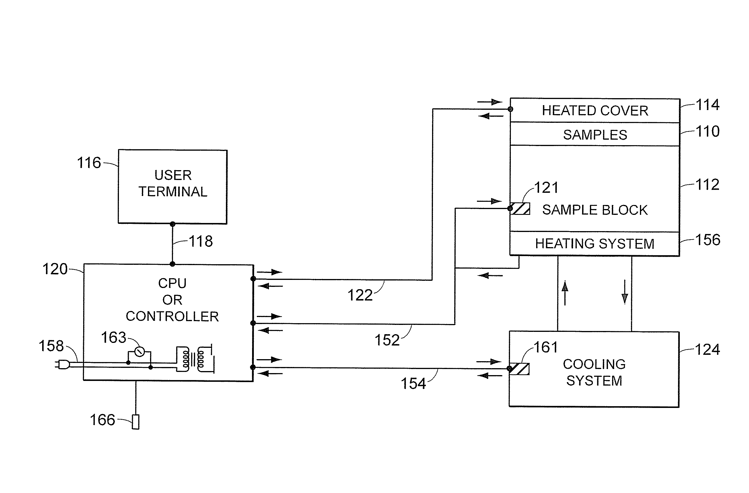
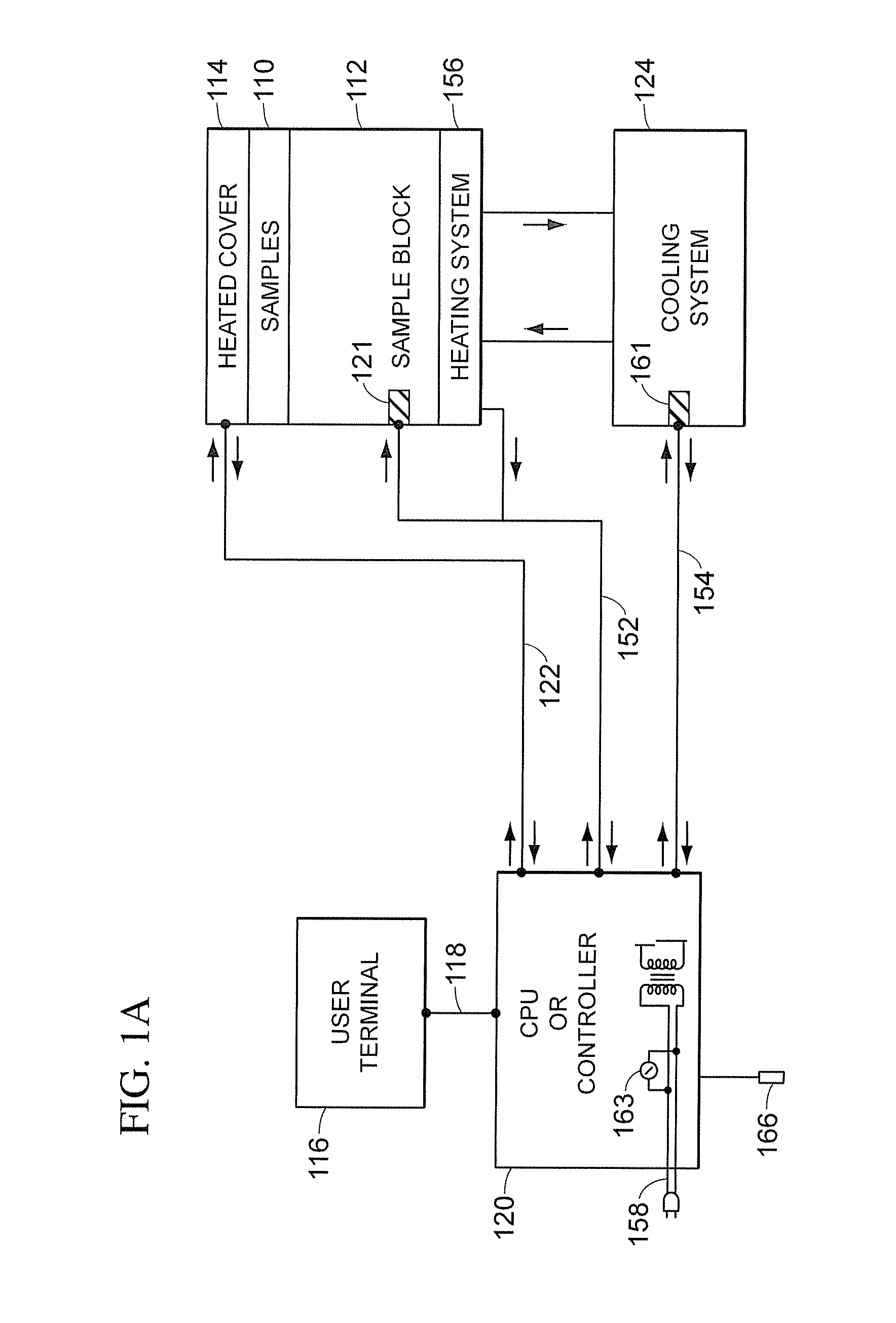
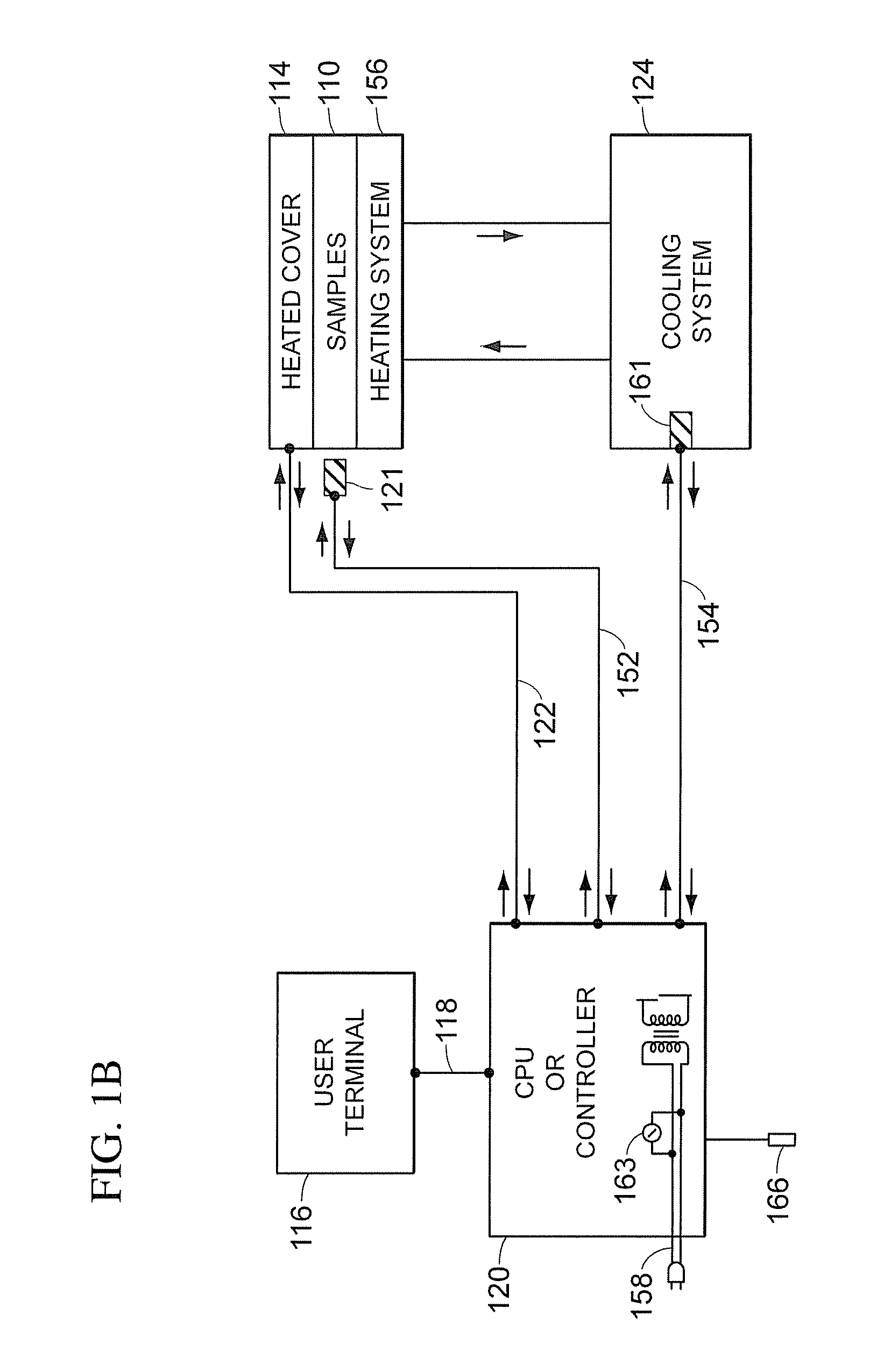
[0042] Referring to FIGS. 1A and 1B, a block diagram of the major...


PUM

PropertyMeasurementUnit
temperaturesaaaaaaaaaa
temperatureaaaaaaaaaa

Abstract

A device for performing polymerase chain reactions using cooling members not used in conventional thermal cyclers. A device for performing polymerase chain reactions may include a sample holder configured to receive a nucleic acid sample, a heating system configured to raise the temperature of the sample, a cooling system configured to lower the temperature of the sample, and a controller configured to operably control the heating system and the cooling system to cycle the device through a desired time-temperature profile. The cooling system may comprise at least one cooling member selected from a synthetic jet ejector array, a vibration-induced droplet atomization system, a vibrating diaphragm system, a piezo fan, a Cold Gun, a microchannel cooling loop, and a Cool Chip.

Description

CROSS REFERENCE TO RELATED APPLICATIONS [0001] This application claims a priority benefit under 35 U.S.C. §119(e) from U.S. Patent Application No. 60 / 816,192 filed Jun. 23, 2006 and Application No. 60 / 816,133 filed Jun. 23, 2006, all of which are incorporated herein by reference.FIELD [0002] This disclosure pertains generally to instruments for performing polymerase chain reactions (PCR). More particularly, this disclosure is directed to systems and methods for cooling in a thermal cycler configured to perform polymerase chain reactions substantially simultaneously on a plurality of samples. INTRODUCTION [0003] To amplify DNA (Deoxyribose Nucleic Acid) using the PCR process, a specially constituted liquid reaction mixture is cycled through a PCR protocol that includes several different temperature incubation periods. The reaction mixture is comprised of various components such as the DNA to be amplified and at least two primers selected in a predetermined way so as to be sufficientl...

Claims


Application Information

Patent Timeline
Patent Type & Authority Applications(United States)
IPC IPC(8): C12P19/34B01J19/00C12M1/38
CPCB01L7/52B01L2300/0636B01L2300/0829B01L2300/185B01L2300/1822B01L2300/1844B01L2300/0877
Inventor OLDHAM, MARK F.HENDERSON, ERIC G.MIRCHANDANI, VINODNORDMAN, ERIC S.HABERSTROH, MARCSLUIS, JOHANNES P.
Owner APPL BIOSYSTEMS INC
Why Eureka
Try Eureka