
Ultrasonic diagnostic apparatus and ultrasonic diagnostic method

a diagnostic apparatus and ultrasonic technology, applied in the field of ultrasonic diagnostic equipment and ultrasonic diagnostic method, can solve the problems of blood flow velocity detection accuracy falling extremely, blood flow velocity may be recognized incorrectly, and it is difficult to calculate blood flow correctly

Inactive Publication Date: 2008-02-28
TOSHIBA MEDICAL SYST CORP
View PDF7 Cites 26 Cited by
  • Summary
  • Abstract
  • Description
  • Claims
  • Application Information

AI Technical Summary

Benefits of technology

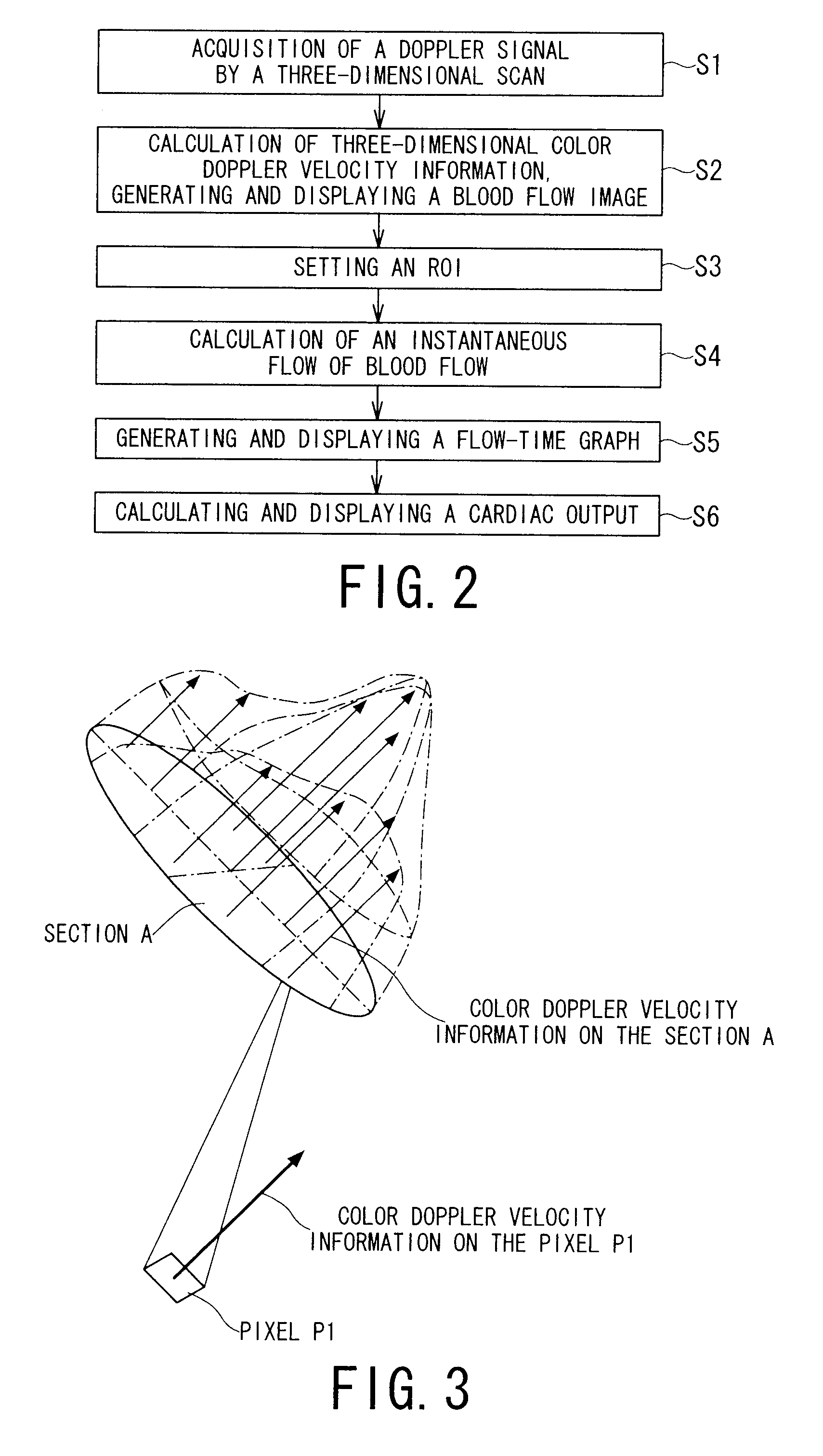
[0025]The ultrasonic diagnostic apparatus and the ultrasonic diagnostic method as described above make it possible to measure a blood flow at a more appropriate region.

Problems solved by technology

For this reason, there is a problem that detection accuracy of a blood flow velocity falls extremely when an angle between a direction of a blood flow and a sound axis of an ultrasonic wave becomes near 90 degrees.
Consequently, there is a possibility that a blood flow velocity may be recognized incorrectly.
Therefore, it may be difficult to calculate a blood flow correctly, depending on a method of scanning, i.e., relative inclination between a direction of a blood flow and a sound axis of an ultrasonic wave, even if a method of calculating a blood flow precisely from velocity information on a three-dimensional blood flow is adopted.
Therefore, realistically, it is in a difficult situation to capture the maximum flow velocity and the maximum blood flow easily because of such a burden occurring.
Therefore, it is difficult to judge whether the cardiac output was measured in suitable accuracy when the cardiac output is measured by integrating with the blood flow of a certain scanning position in the direction of time.

Method used


Image

  • Ultrasonic diagnostic apparatus and ultrasonic diagnostic method
  • Ultrasonic diagnostic apparatus and ultrasonic diagnostic method
  • Ultrasonic diagnostic apparatus and ultrasonic diagnostic method

Examples


Embodiment Construction

[0049]An ultrasonic diagnostic apparatus and an ultrasonic diagnostic method according to embodiments of the present invention will be described with reference to the accompanying drawings.

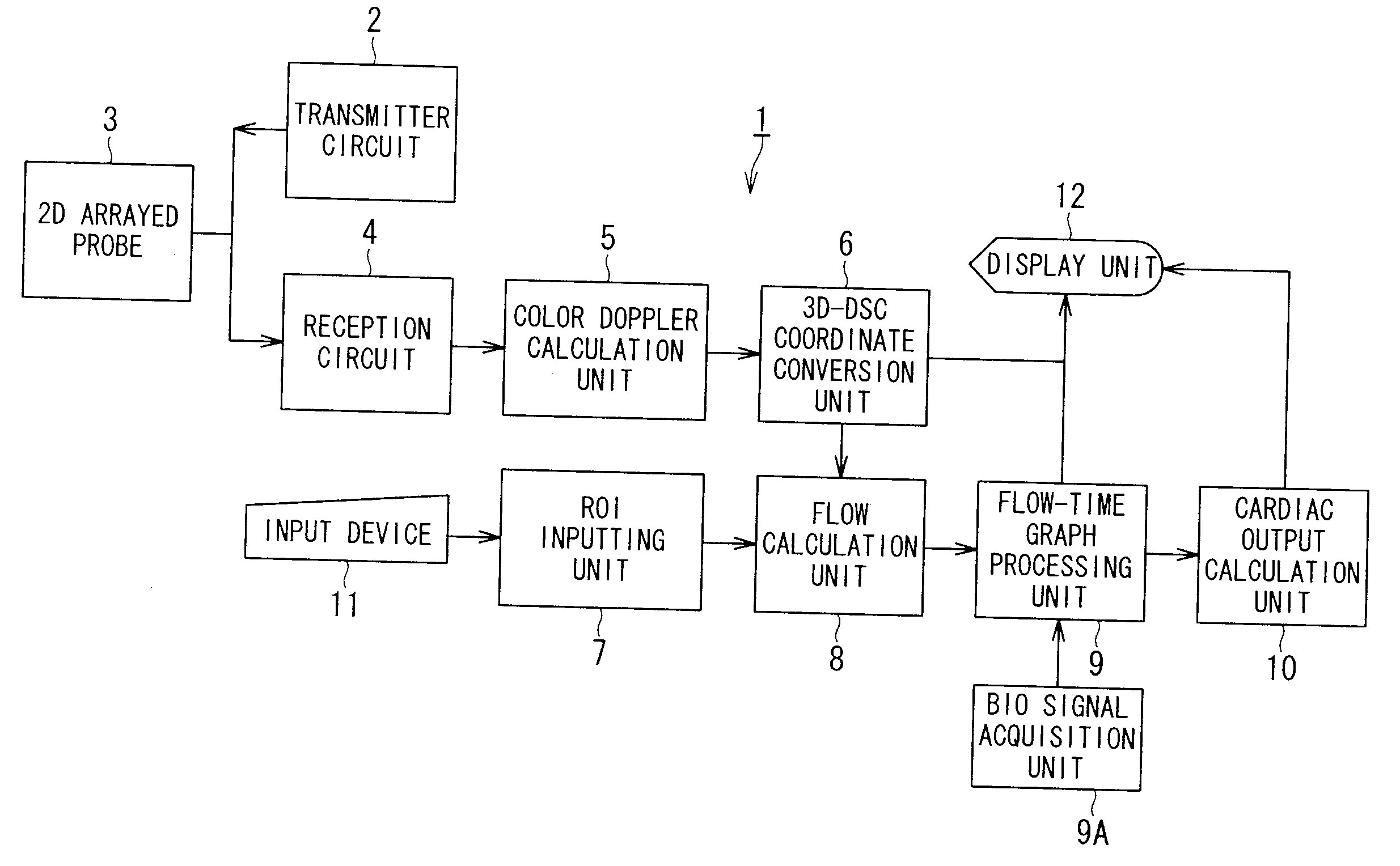
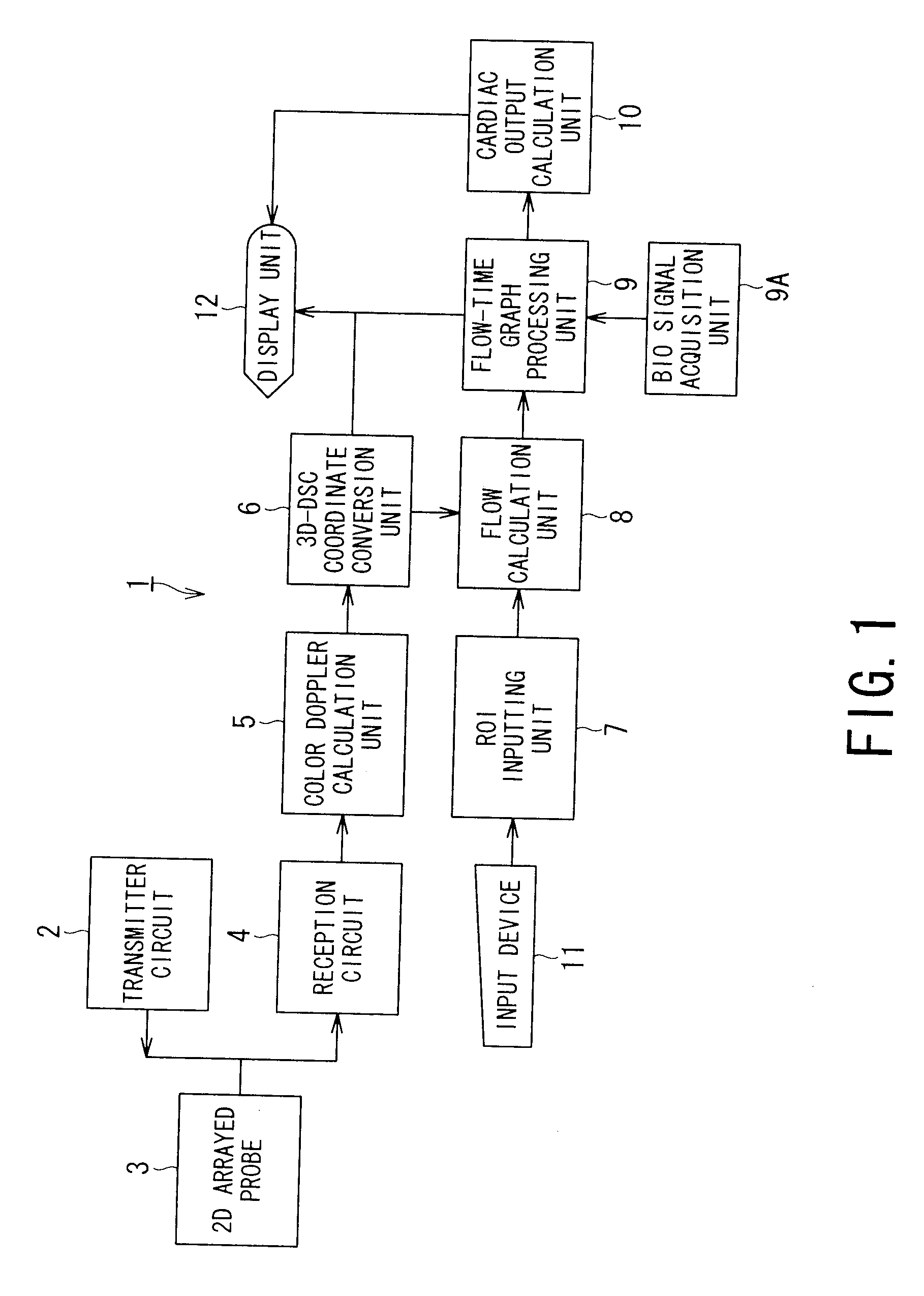
[0050]FIG. 1 is a functional block diagram showing an ultrasonic diagnostic apparatus according to an embodiment of the present invention.

[0051]An ultrasonic diagnostic apparatus 1 includes a transmitter circuit, a 2D (two-dimensional) arrayed probe 3, a reception circuit 4, a color Doppler calculation unit 5, 3D-DSC (three-dimensional-digital scan converter) coordinate conversion unit 6, an ROI (region of interest) inputting unit 7, a flow calculation unit 8, a flow-time graph processing unit 9, a cardiac output calculation unit 10, an input device 11 and a display unit 12. Each element can be configured by a circuit or a computer in which program is installed.

[0052]The transmitter circuit 2 has functions to generate a pulse signal as a transmission signal so that an ultrasonic wave may be transm...


PUM


Abstract

An ultrasonic diagnostic apparatus includes a Doppler velocity information acquiring unit, a region-of-interest-setting unit and an instantaneous flow calculating unit. The Doppler velocity information acquiring unit is configured to acquire three-dimensional Doppler velocity information from an object by a three-dimensional scan with transmission and reception of an ultrasonic wave. The region-of-interest-setting unit is configured to set a region of interest spatially. The instantaneous flow calculating unit is configured to calculate an instantaneous blood flow in the region of interest with using the three-dimensional Doppler velocity information.

Description

BACKGROUND OF THE INVENTION[0001]1. Field of the Invention[0002]The present invention relates to an ultrasonic diagnostic apparatus and an ultrasonic diagnostic method for obtaining three-dimensional blood flow information by acquiring a Doppler signal from an object, and more particularly, to an ultrasonic diagnostic apparatus and an ultrasonic diagnostic method which display a time variation of blood flow quantity obtained by integrating pieces of velocity information of a blood flow.[0003]2. Description of the Related Art[0004]An ultrasonic diagnostic apparatus is an image diagnostic apparatus which obtains a tomographic image of a tissue in an object by transmitting and receiving an ultrasonic wave into and from the object without invasiveness. A technique of measuring a velocity of a blood flow or a tissue in an object using Doppler effect of an ultrasonic wave among ultrasonic diagnoses is called to an ultrasonic Doppler method. Further, an ultrasonic Doppler method using an u...

Claims


Application Information

Patent Timeline
IPC IPC(8): A61B8/00
CPCA61B5/0402A61B8/065A61B8/483A61B8/469A61B8/488A61B8/4483A61B5/318A61B5/33
Inventor KATAGUCHI, MUNEKIKAWAGISHI, TETSUYAABE, YASUHIKOHASHIMOTO
Owner TOSHIBA MEDICAL SYST CORP
Learn More