
Needle syringe having some disposable components

Inactive Publication Date: 2008-02-28
WANG HSIEN TSUNG +1
View PDF0 Cites 42 Cited by
  • Summary
  • Abstract
  • Description
  • Claims
  • Application Information

AI Technical Summary

Benefits of technology

[0007]It is therefore one object of the present invention to provide a needle syringe having windows formed on a surface of its barrel for enabling a medical worker to clearly view the volume of fluid in a medicine cartridge through windows during injection so as to make a correct determination of when to stop the injection.
[0008]It is another object of the present invention to provide a needle syringe which after use and after a simple disassembly some components including a tube, a medicine cartridge, and a double needle thereof are discarded as a whole for reducing the risk of spreading blood-borne diseases, and the remaining components including a barrel, a wing, and a handle assembly adapted to re-use for being cost-effective.
[0009]It is a further object of the present invention to provide a needle syringe including a tube having a plurality of equally spaced lengthwise ribs around its inner surface so as to form a tapered surface or tapered surface inner barrel for fastening a forward plug of a medicine cartridge mounted in a barrel. Thus, the medicine cartridge is prohibited from slipping relative to the barrel when a plunger is sliding in the medicine cartridge toward the plug for dispensing fluid.

Problems solved by technology

However, a patient may be contaminated by the re-used needle syringe if the sterilization is not complete.
Moreover, the double needle 95 may accidentally prick the medical worker with microorganisms while removing.
This is not desirable.
As a result, a correct determination of when to stop the injection is made impossible.
However, discarding a great number of needle syringes after use is not cost-effective and may further pollute the environment if they are not disposed properly.

Method used


Image

  • Needle syringe having some disposable components
  • Needle syringe having some disposable components
  • Needle syringe having some disposable components

Examples


Embodiment Construction

[0029]Referring to FIGS. 4 to 7, a needle syringe in accordance with a first preferred embodiment of the invention is shown. The needle syringe comprises a barrel and needle assembly 10, a wing 20, a handle assembly 30, and a medicine cartridge 40. Each component is discussed in detailed below. The barrel and needle assembly 10 comprises a hollow, cylindrical barrel 11 including a forward externally threaded extension 112, a lengthwise first window 113 formed on a surface of the barrel 11, and a pivot 111 for pivotably securing a rear end of the barrel 11 to the wing 20. As such, the wing 20 is adapted to turn about 90-degree relative to the barrel 11 for mounting the medicine cartridge 40 in the barrel and needle assembly 10 as detailed later.

[0030]The barrel and needle assembly 10 further comprises a transparent tube 12 including rear internal threads 121, a lengthwise second window 122 formed on a surface of the transparent tube 12, a forward nose 123 having external threads, an ...


PUM


Abstract

A needle syringe in one embodiment includes a needle assembly including front and rear hypodermic needles; a barrel including a first window; a tube threadedly secured to the barrel and the needle assembly respectively and including a second window and an inner circumferential tapered surface; a medicine cartridge including a rear plunger and a front plug secured to the tapered surface when the cartridge is mounted in the barrel; and a handle. The rear needle passes the tube and the plug into the cartridge. The cartridge is prohibited from slipping relative to the barrel during injection. A medical worker can view the volume of fluid in the cartridge through the windows so as to correctly determine when to stop injection. After use the tube, the cartridge, and the needle assembly are removed to be discarded, and the barrel, the wing, and the handle are adapted to re-use.

Description

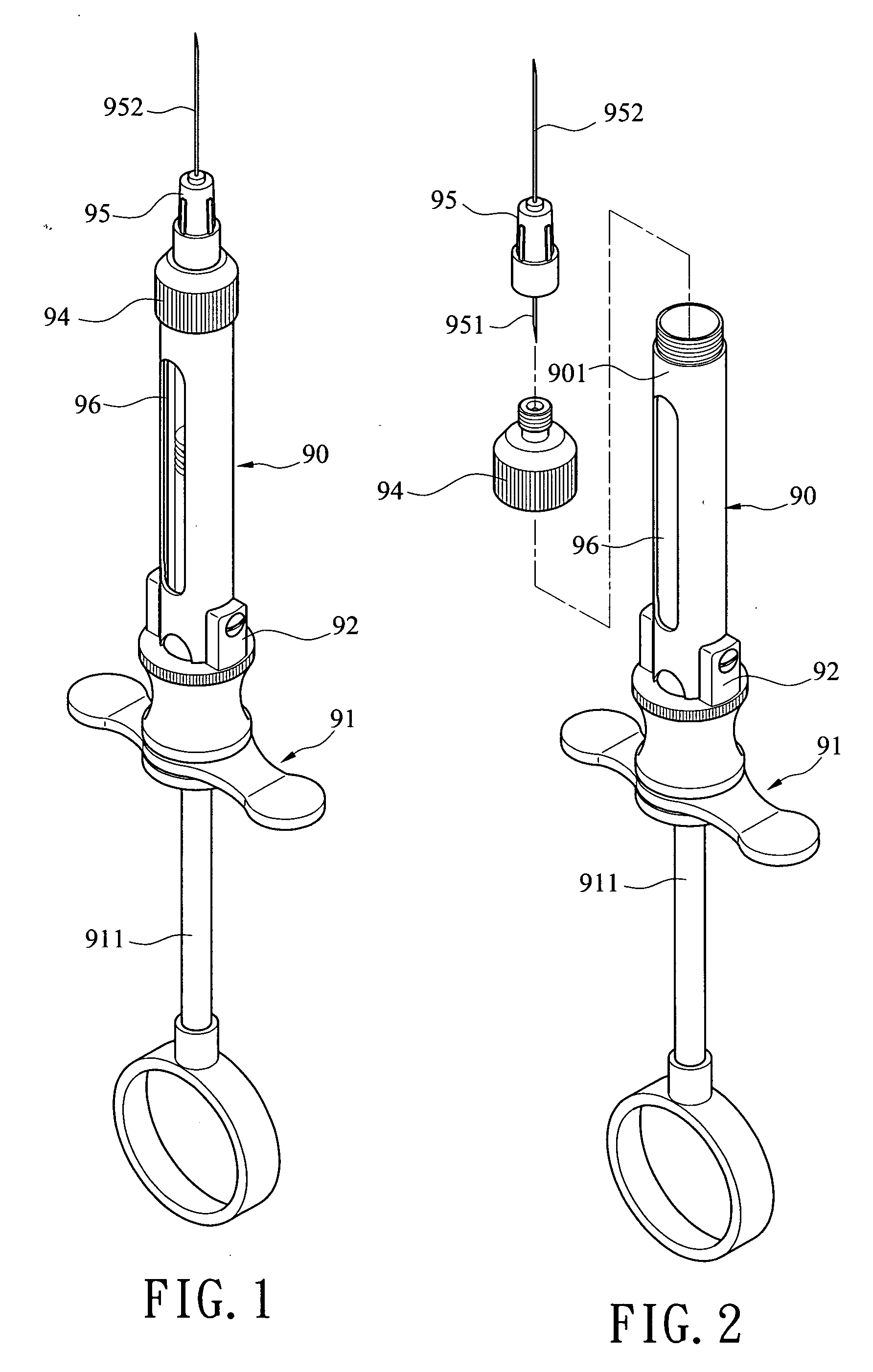
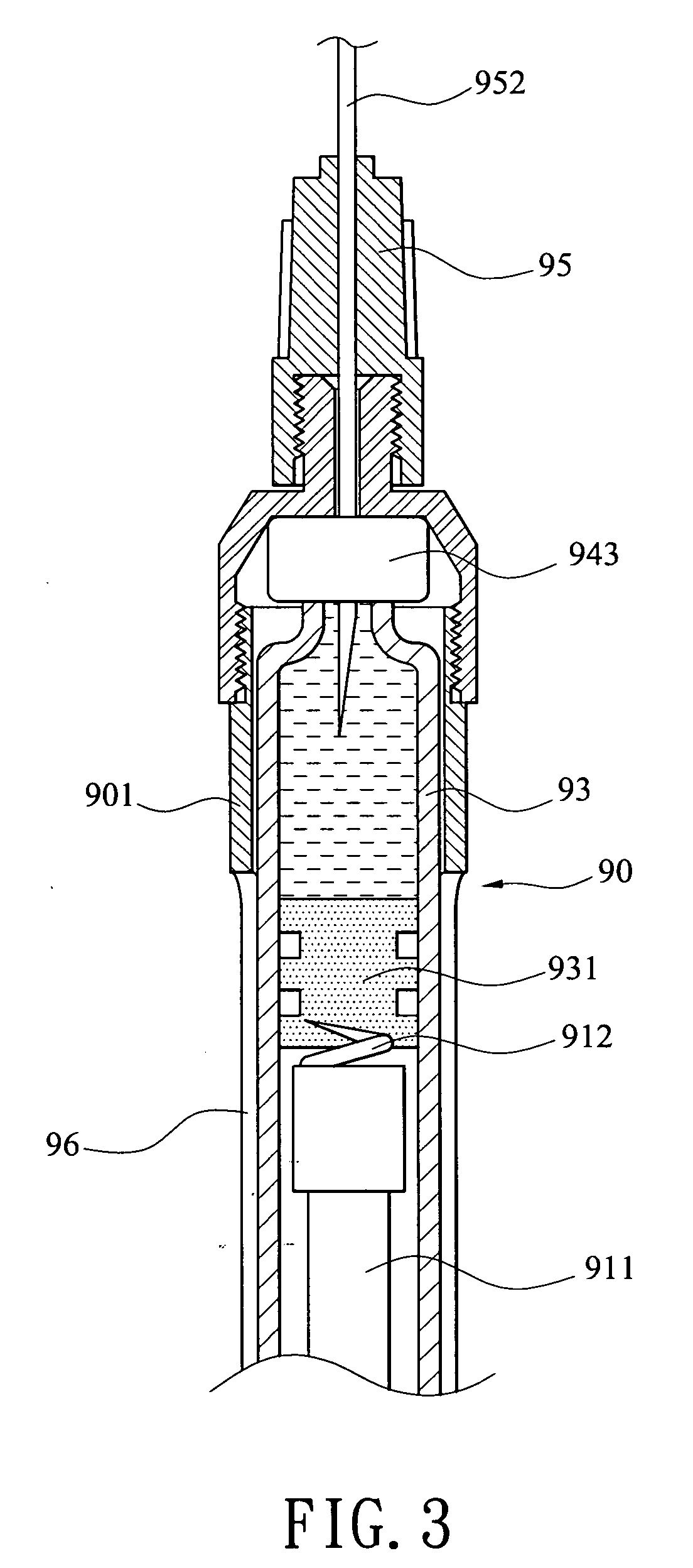
BACKGROUND OF THE INVENTION[0001]1. Field of Invention[0002]The present invention relates to needle syringes and more particularly to such a needle syringe which after use and after a simple disassembly some components including a tube, a medicine cartridge, and a double needle are discarded as a whole for reducing the risk of spreading blood-borne diseases, and the remaining components including a barrel, a wing, and a handle assembly adapted to re-use by sterilization for being cost-effective.[0003]2. Description of Related Art[0004]A conventional needle syringe is shown in FIGS. 1, 2, and 3. The needle syringe comprises a barrel 90, a wing 91, and a pivot 92 for pivotably securing a rear end of the barrel 90 to the wing 91. As such, the wing 91 is adapted to turn about 90-degree relative to the barrel 90 for mounting an anesthetic cartridge 93 in the barrel 90. The barrel 90 comprises a detachable head 94 having interior threads adapted to threadably secure to outer threads on a ...

Claims


Application Information

Patent Timeline
IPC IPC(8): A61M5/00
CPCA61M5/24A61M5/3137A61M5/31515A61M5/3272A61M5/347A61M2205/583A61M2005/2411A61M2005/2496A61M2005/3247A61M2005/3253A61M2005/2407A61M5/162
Inventor CHENG, WAN CHANG
Owner WANG HSIEN TSUNG
Features
  • Generate Ideas
  • Intellectual Property
  • Life Sciences
  • Materials
  • Tech Scout
  • Unparalleled Data Quality
  • Higher Quality Content
  • 60% Fewer Hallucinations
Learn More