Cupping jar with lamp

Inactive Publication Date: 2008-02-28
CHO YUN SANG
View PDF0 Cites 3 Cited by
  • Summary
  • Abstract
  • Description
  • Claims
  • Application Information

AI Technical Summary

Benefits of technology

[0022]In order to prevent the cupping jar from slipping due to sweat on the palms when the operator takes the cupping jar, a handle portion 2 is provided. Accordingly, cupping treatment can

Problems solved by technology

During the cupping treatment, the temperature of the fire cupping jar generally incre

Method used


Image

  • Cupping jar with lamp
  • Cupping jar with lamp
  • Cupping jar with lamp

Examples


Embodiment Construction

[0037]Hereinafter, a fire cupping jar according to the embodiments of the invention will be described in detail with reference to the drawings.

[0038]The term “fire cupping jar” used herein refers to a cupping jar, in which a vacuum in a cupping jar is caused by fire.

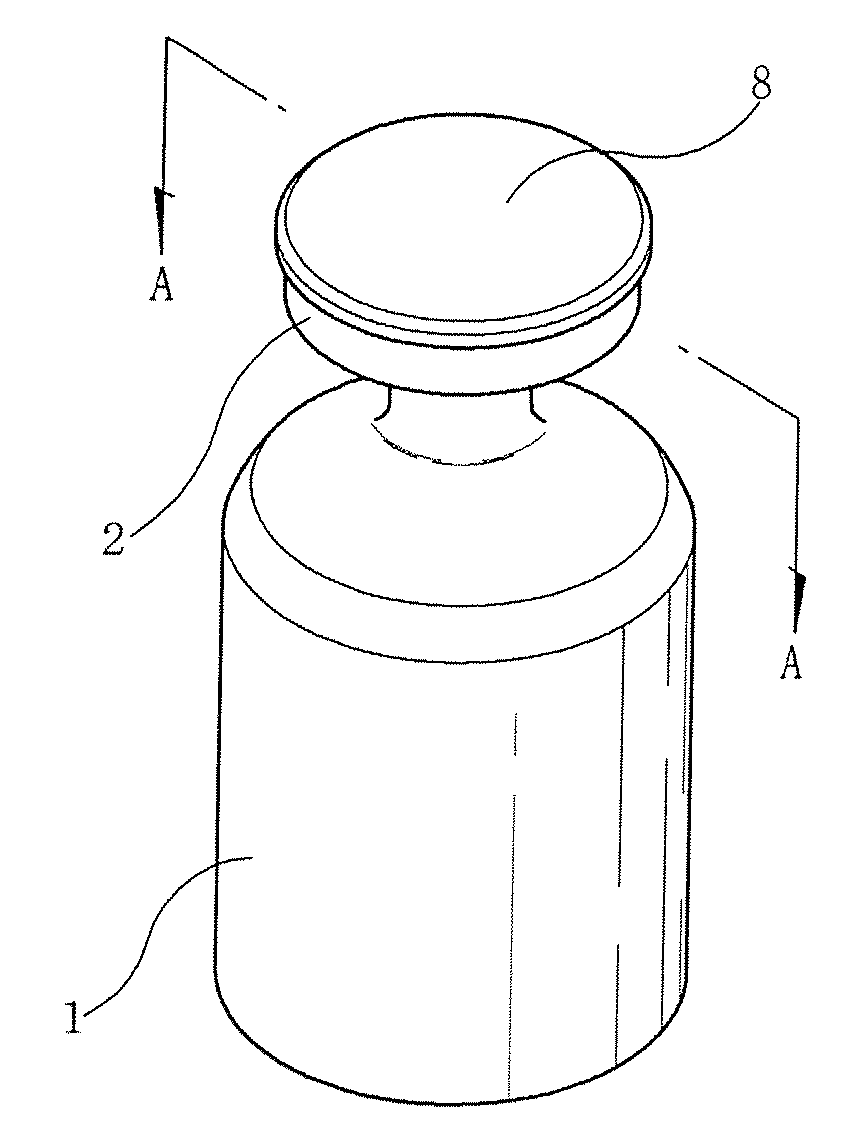
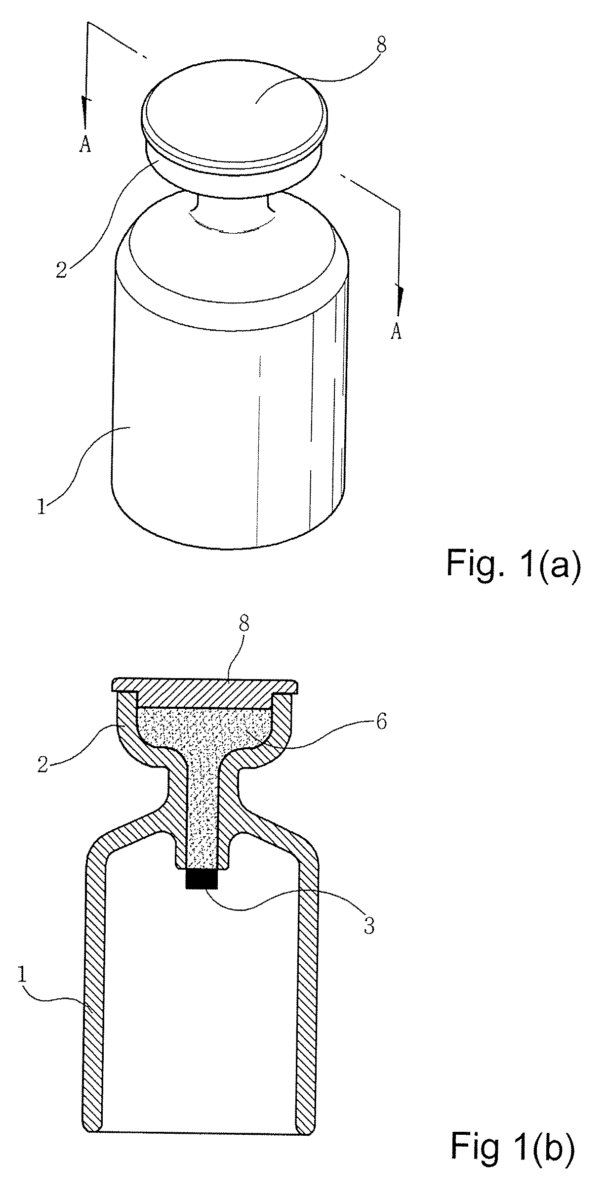
[0039]FIG. 1 is a cross-sectional view and a perspective view showing a cupping jar according to an embodiment of the invention. Referring to FIG. 1, a lamp 6 is provided in a handle portion 2. The lamp 6 is filled with an alcohol-soaked cotton 9 or a porous material such that a large amount of alcohol is stably maintained. In order to stably fix a combustion core 3 and the alcohol-soaked cotton 9, an inner wall surface of the lamp may be jagged (not shown). The combustion core 3 is exposed outside the lamp 6 by a predetermined length, such that a uniform flame is maintained in the cup portion 1.

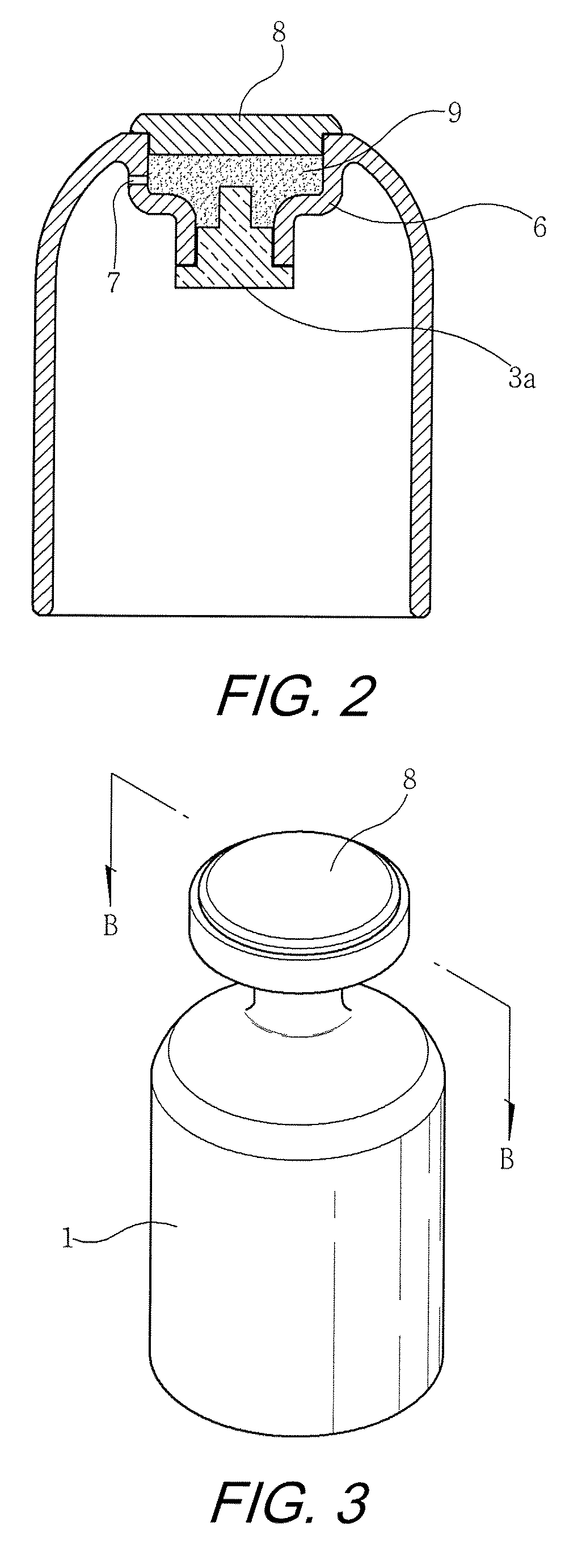
[0040]FIG. 2 is an explanatory view of a lamp in a cupping jar according to an embodiment of the invention. Referring to FIG. 2...


PUM


Abstract

A fire cupping jar includes a cup portion and a lamp that is provided in the cupping jar. The cupping jar can be repeatedly used without needing to be replenished with alcohol and can use fire capable of providing uniform flame.

Description

CROSS-REFERENCE TO RELATED APPLICATION[0001]This application claims under 35 U.S.C. §119(a) on Korean Patent Application No. 10-2006-0088507 filed on Aug. 28, 2006 and Korean Patent Application No. 10-2006-0088508 filed on Sep. 1, 2006, the entire contents of which are incorporated herein by reference.BACKGROUND OF THE INVENTION[0002](a) Field of the Invention[0003]The present invention relates to a cupping jar that can be repeatedly used without needing to be replenished with alcohol and can use fire capable of providing uniform flame.[0004](b) Background Art[0005]Cupping therapy is a medical treatment that forms negative pressure inside a cupping jar using heat or a negative pressure device, and places the cupping jar on the skin so as to draw blood, to cause local congestion, or to apply a physical stimulus, thereby treating a disease. The kinds of cups used for cupping are small cups, bowls, or drums. Cupping therapy is widely used for treating traumatic diseases such as a simpl...

Claims


Application Information

Patent Timeline
IPC IPC(8): A61B17/00A61B19/00B65D25/28
CPCA61B2017/00561A61H9/005A61H9/0057A61N2005/066A61H2201/025A61H2201/0278A61H2201/10A61H2201/0207
Inventor CHO, YUN-SANG
Owner CHO YUN SANG
Why Eureka
Try Eureka