Brake device

Active Publication Date: 2008-03-06
HONDA MOTOR CO LTD
View PDF10 Cites 37 Cited by
  • Summary
  • Abstract
  • Description
  • Claims
  • Application Information

AI Technical Summary

Benefits of technology

[0008]It is accordingly an object of an embodiment of the present invention to provide a brake device which can be reduced in weight

Problems solved by technology

In the above conventional structure wherein the radial projection is formed at the end portion of the caliper bracket to remove the dirt from the space between the rim and the flange, there is a problem such that the caliper bracket formed of metal is inc

Method used


Image

  • Brake device
  • Brake device
  • Brake device

Examples


Embodiment Construction

[0028]A preferred embodiment of the present invention will now be described with reference to the drawings. In the description and drawings of the present invention, the terms of “front,”“rear,”“right,”“left,”“upper,” and “lower” are used with respect to the vehicle. Further, these terms are used with respect to a mounted condition on the vehicle body.

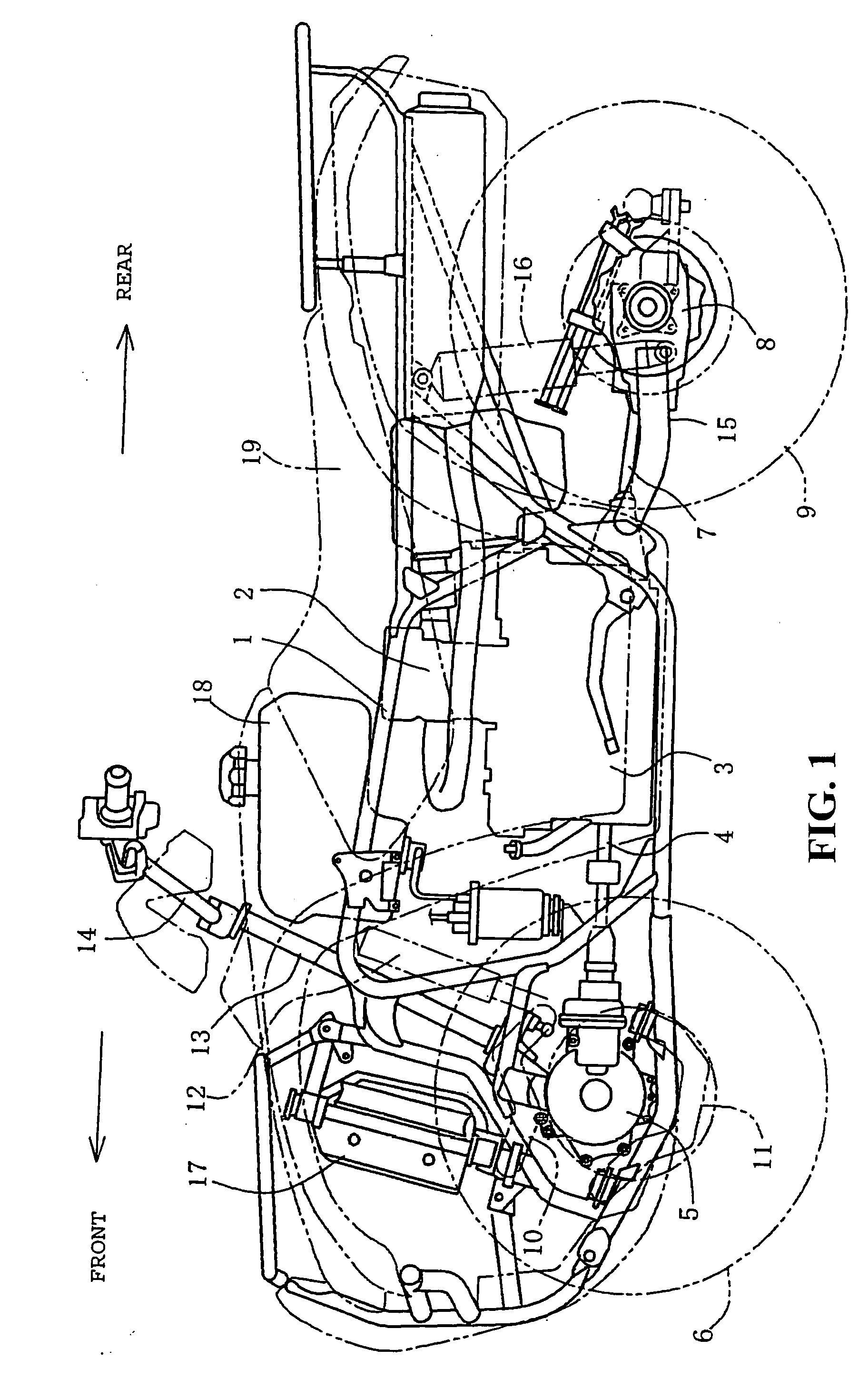
[0029]FIG. 1 is a side view of an off-road vehicle according to a preferred embodiment of the present invention. This off-road vehicle is a saddle seat type four-wheel drive vehicle having low-pressure balloon tires. An engine 2 and a transmission 3 are mounted on a body frame 1 at a central portion thereof. A front drive shaft 4 extends to the front from the transmission 3 to transmit engine power through a front gear box 5 to right and left front wheels 6. Similarly, a rear drive shaft 7 extends to the rear from the transmission 3 to transmit engine power through a rear gear box 8 to right and left rear wheels 9.

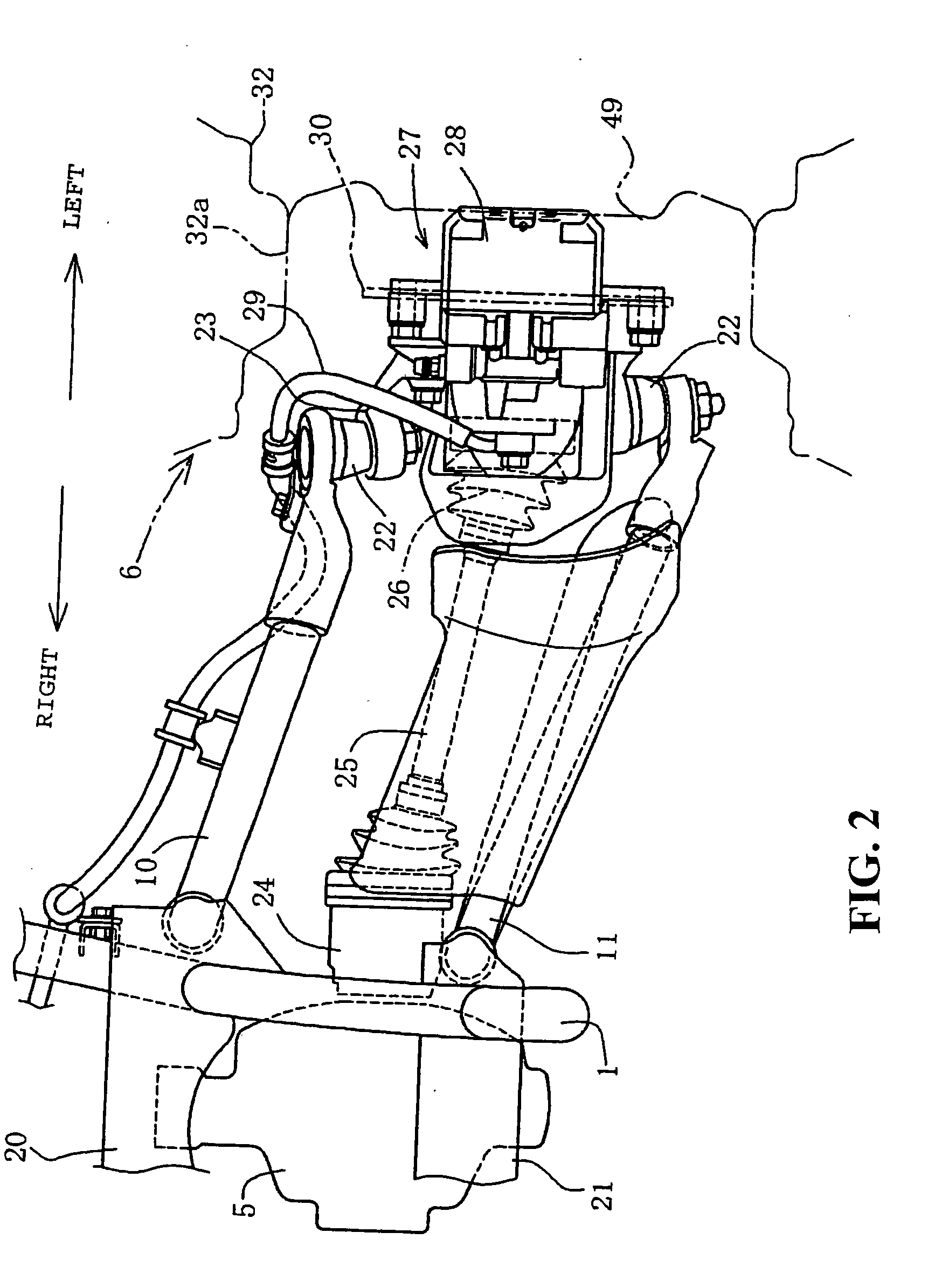
[0030]Each front whee...


PUM


Abstract

A brake disc guard is provided inside of a rim of a front wheel and mounted on a knuckle. A caliper is located in a cutout portion formed at a front portion of the brake disc guard. The caliper is supported through a caliper bracket to the knuckle. A large-diameter portion is formed at an upper front end portion of the brake disc guard. The large-diameter portion extends so as to cover the upper side of the caliper bracket and the caliper. A scraper is formed at the front end of the large-diameter portion so as to be bent radially outwardly. The spacing a between the rim and the scraper is set to be the smallest. The dirt deposited on the rim is scraped off by the scraper, so that the dirt separated from the rim is prevented from falling onto the caliper.

Description

CROSS-REFERENCE TO RELATED APPLICATIONS[0001]The present application claims priority under 35 USC 119 to Japanese Patent Application No. 2006-236957 filed on Aug. 31, 2006 the entire contents of which are hereby incorporated by reference.BACKGROUND OF THE INVENTION[0002]1. Field of the Invention[0003]The present invention relates to a brake device suitable for use in an off-road vehicle. More particularly to a brake device having a cover member for covering a brake disc.[0004]2. Description of Background Art[0005]An off-road vehicle having a wheel-in disc brake structure such that a disc brake is provided inside of a rim of a wheel is known wherein a brake disc guard for covering a disc of the disc brake is provided and wherein the side surface of the brake disc guard at an upper portion thereof is formed with a flange extending in a circumferential direction along the outer circumference of the disc and projecting sideward so as to cover the outer circumference of the disc. In such...

Claims


Application Information

Patent Timeline
IPC IPC(8): F16D65/00
CPCF16D2055/0037F16D55/00
Inventor NAKAMURA, KOSHITODA, MAKOTOKIKUCHI, TETSUYOSHI
Owner HONDA MOTOR CO LTD
Why Eureka
Try Eureka