Electronic pen and electronic pen system

a pen and electronic technology, applied in the field of electronic pen and electronic pen system, can solve the problems of inability to obtain correct information, large conventional battery for charging, and inability to grasp the precise positional relation of plural image data, etc., and achieve the effect of accurate reading information, small and light-weight writing instruments, and large rechargeable batteries

Inactive Publication Date: 2008-03-06
SEMICON ENERGY LAB CO LTD
View PDF42 Cites 123 Cited by
  • Summary
  • Abstract
  • Description
  • Claims
  • Application Information

AI Technical Summary

Benefits of technology

[0025]By the present invention, it is possible to provide a writing instrument which can accurately read information written in a display portion as electronic information without using an image sensor and which can store the electronic information. Further, since the writing instrument is wirelessly supplied with an electric power from the outside to charge

Problems solved by technology

Therefore, when one character is larger than the image data that can be taken at one time, it is hard to grasp the precise positional relation of pl

Method used


Image

  • Electronic pen and electronic pen system
  • Electronic pen and electronic pen system
  • Electronic pen and electronic pen system

Examples


embodiment mode 1

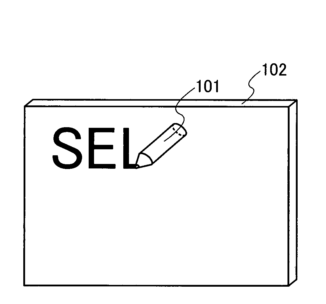
[0049]Embodiment Mode 1 will describe a structure of a writing instrument which can read information written in a display portion such as a whiteboard as electronic data.

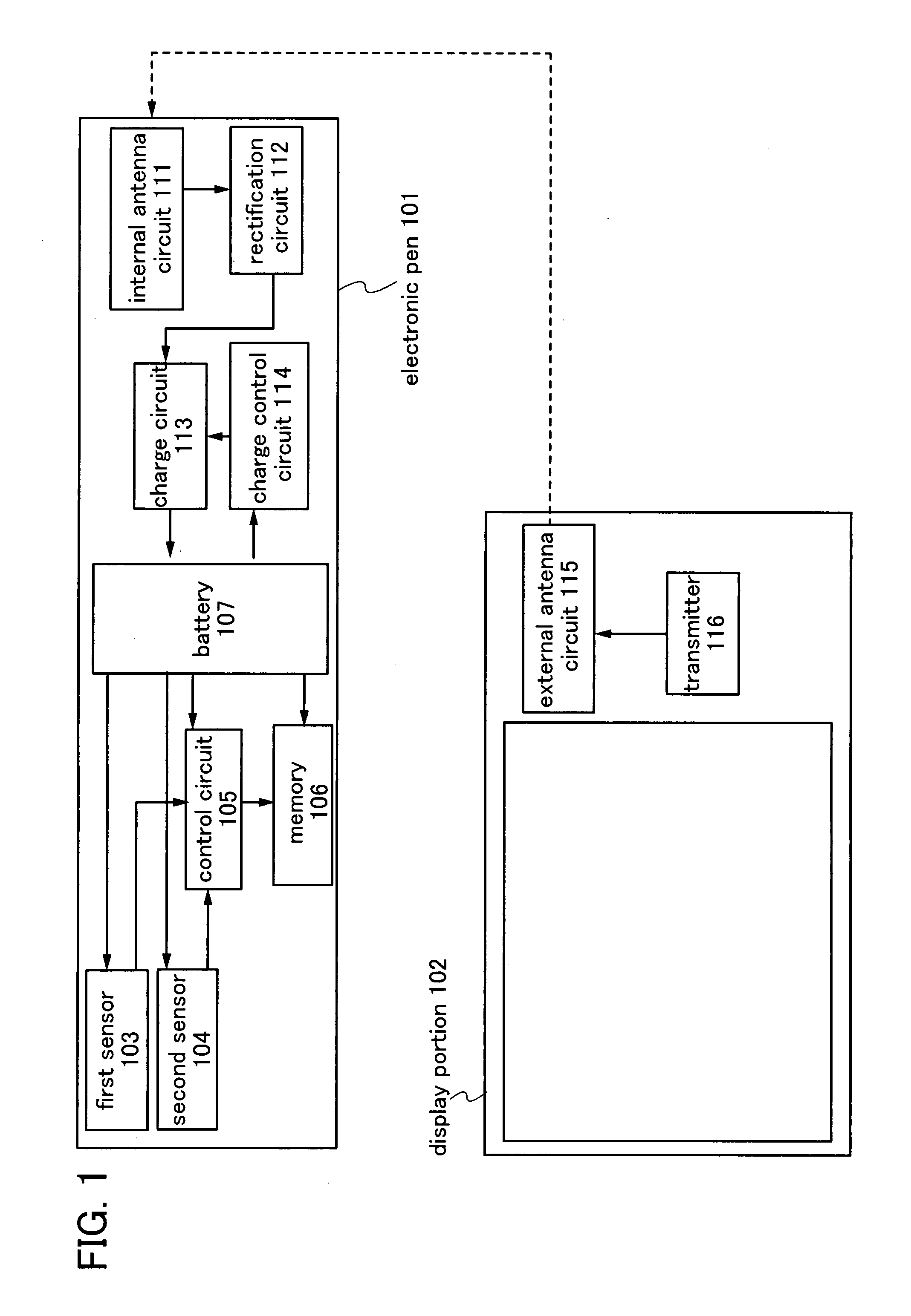
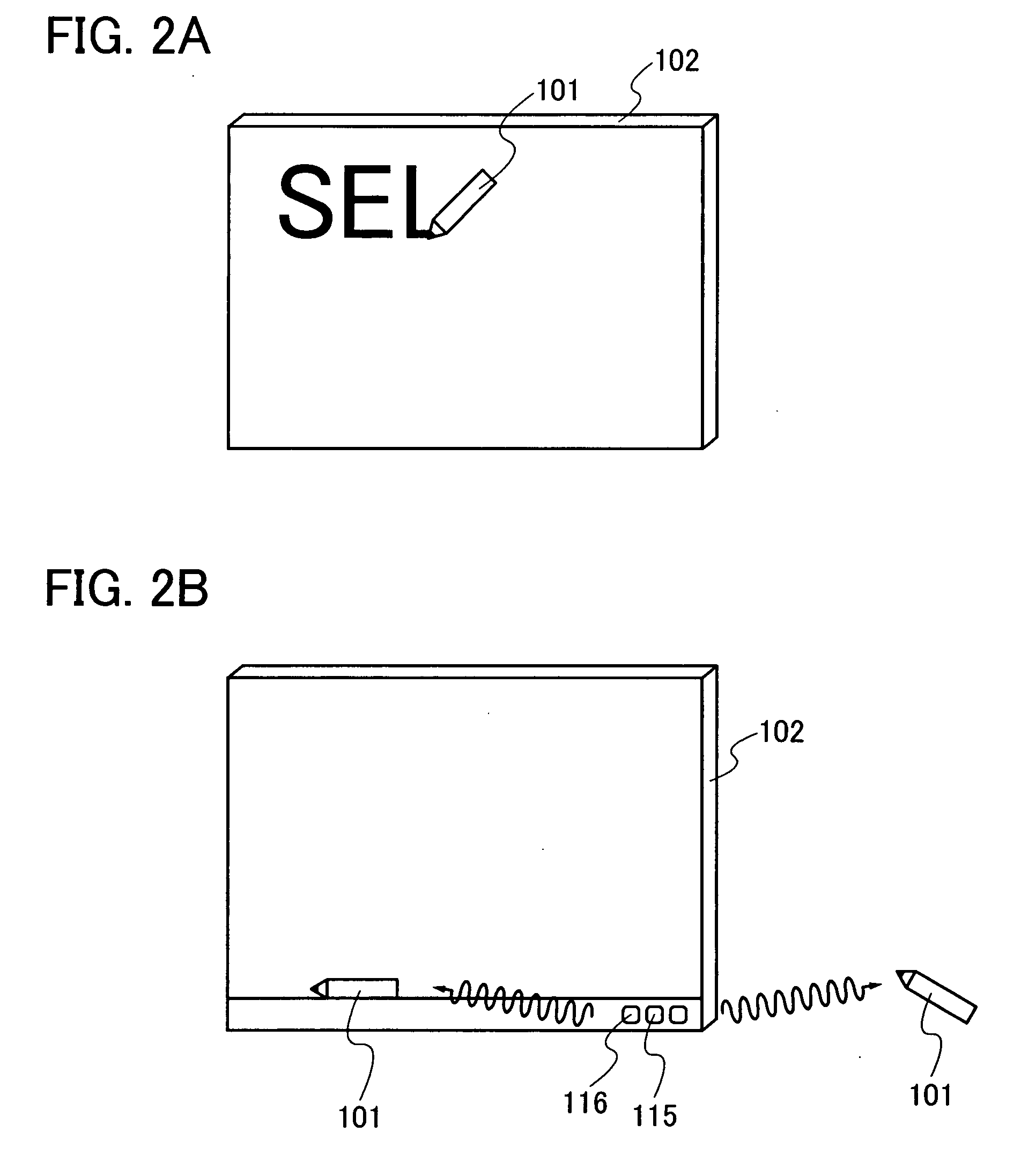
[0050]The writing instrument of the present invention will be described with reference to FIG. 1. FIG. 1 shows an embodiment mode of an electronic pen 101 and a display portion 102 as writing instruments according to Embodiment Mode 1. The electronic pen 101 includes a first sensor 103, a second sensor 104, a control circuit 105, a memory 106, a battery 107, an internal antenna circuit 111, a rectification circuit 112, a charge circuit 113, and a charge control circuit 114. In addition, the display portion 102 includes an external antenna circuit 115 and a transmitter 116.

[0051]An output terminal of the internal antenna circuit 111 is electrically connected to an input terminal of the rectification circuit 112, an output terminal of the rectification circuit 112 is electrically connected to an input terminal of the ...

embodiment mode 2

[0080]Embodiment Mode 2 will describe a structure of an electronic pen described in the above embodiment mode, with reference to the drawings.

[0081]In this embodiment mode, an electronic pen includes a body 601, an internal antenna 603, a battery 604, a circuit substrate 605, a first sensor 606, a second sensor 607, a pen nib 608, and a pen barrel 609 (FIG. 4). Note that the internal antenna 603, the battery 604, the circuit substrate 605, the first sensor 606, and the second sensor 607 are electrically connected with wires. Since the electronic pen of this embodiment mode wirelessly obtains electric power, in the case of providing the internal antenna inside the electronic pen, an electromagnetic wave needs to reach the inside of the electronic pen. In that case, the body 601 is preferably formed using an insulator which allows electromagnetic waves to pass. For example, the body 601 can be formed using a resin. Further, if a loop antenna is used as the internal antenna, electromag...

embodiment mode 3

[0095]Next, Embodiment Mode 3, which is different from the embodiment mode of FIG. 1, will be described with reference to FIGS. 5 to 7. An electronic pen 101 shown in FIG. 5 has a structure in which a remaining amount detection circuit 402 and a modulation circuit 401 are added to the structure of the embodiment mode shown in FIG. 1.

[0096]An electric charge stored in a battery 107 shown in FIG. 1 decreases gradually as the electronic pen continues operation. Then, the voltage of the battery 107 also decreases gradually. At the time when the voltage of the battery 107 becomes lower than minimum operating voltages of a first sensor 103, a second sensor 104, a control circuit 105, and a memory 106, the electronic pen 101 cannot operate and data cannot be stored in the memory. To overcome this problem, a structure of charging the electronic pen 101 in response to detection of battery shortage in the electronic pen 101 will be described.

[0097]FIG. 6 is a block diagram of the remaining am...


PUM


Abstract

To provide a small and light-weight writing instrument that can accurately read information written down on a display portion as electronic information. A pen-shaped device which includes a battery capable of being charged wirelessly from the outside, a first sensor which detects whether a pen nib has contact with a surface, a second sensor which detects movement of the pen nib in contact with the surface, a control circuit which is electrically connected to the first sensor and the second sensor, and a memory which is electrically connected to the control circuit, where the first sensor, the second sensor, the control circuit, and the memory operate by supply of electric power from the battery.

Description

BACKGROUND OF THE INVENTION[0001]1. Field of the Invention[0002]The present invention relates to a writing instrument by which a character or the like is written on a display portion, and a technique which digitizes information written with the writing instrument.[0003]2. Description of the Related Art[0004]Conventionally, in using a whiteboard at a meeting or the like, the content written down on the whiteboard by a writer with a whiteboard marker is stored in such a way that information written down on the whiteboard is read by an image sensor such as a scanner mounted on the whiteboard and is printed on recording paper. Further, in the case where the information written down on the whiteboard is shared by multiple people, a copy of the recording paper is distributed to each person.[0005]Since the method of storing information written down on a conventional whiteboard is limited to making a hard copy on recording paper only, there is a problem in that long-term storage of the info...

Claims


Application Information

Patent Timeline
IPC IPC(8): G06F3/033
CPCG06F3/03545G06F3/0442G06F3/0445G06F3/033G06F3/03542G06F3/04883G06V30/32G06V30/1423
Inventor OSADA, TAKESHIYAMAGUCHI, MAYUMIIZUMI, KONAMI
Owner SEMICON ENERGY LAB CO LTD
Why Eureka
Try Eureka