
Closed Loop Feedback Control to Maximize Stereo Separation in 3D Imaging Systems

a feedback control and stereo separation technology, applied in the field of three-dimensional (“ 3d”) image projection apparatus, can solve the problems of prior art not working for all types of video input such as line interleaved video streams, synchronization not necessarily always achieved, and affecting the quality of video output. , to achieve the effect of low implementation cos

Inactive Publication Date: 2008-03-06
IBM CORP
View PDF34 Cites 18 Cited by
  • Summary
  • Abstract
  • Description
  • Claims
  • Application Information

AI Technical Summary

Benefits of technology

The present invention is a method and apparatus for generating stereoscopic three-dimensional images using a light source and a magnetomechanically actuated alternating filter to polarize the projected images. The system uses polarized filters to create separate left and right eye views, which are then alternated to create a 3D effect. The system is compatible with different types of video input or image data sources and can be used with legacy projection devices. The invention allows for maximum separation between the left and right eye views and provides a cost-effective solution for generating 3D imaging. The viewer wears polarizing eyeglasses to create the 3D experience. The technical effects of the invention include improved depth of field, reduced interference from the projector, and compatibility with various video input sources.

Problems solved by technology

This synchronization is not necessarily always achieved simply by accessing the electronic signals used to control the color filter wheel.
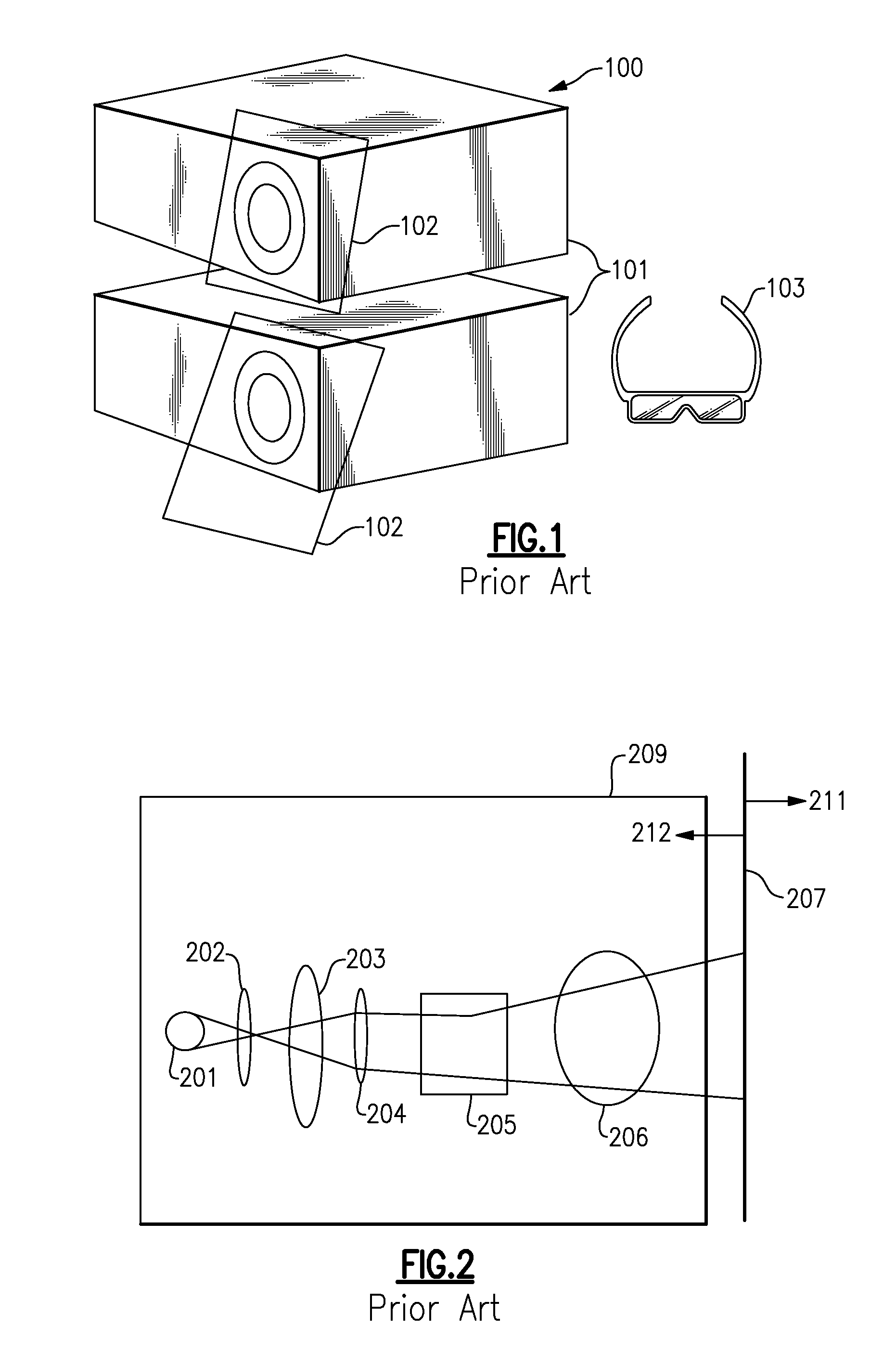
Thus, the projection lenses and other optics may corrupt the polarization encoded image signal.
This prior art will not work for all types of video input such as line interleaved video streams.
These solutions also tend to be expensive, are only practical for a limited number of users at one time, and tend to induce eye strain after prolonged use.
This means that special optics must be used, and polarization sensitive coatings must be avoided, thereby increasing both the complexity and implementation cost.

Method used


Image

  • Closed Loop Feedback Control to Maximize Stereo Separation in 3D Imaging Systems
  • Closed Loop Feedback Control to Maximize Stereo Separation in 3D Imaging Systems
  • Closed Loop Feedback Control to Maximize Stereo Separation in 3D Imaging Systems

Examples


Embodiment Construction

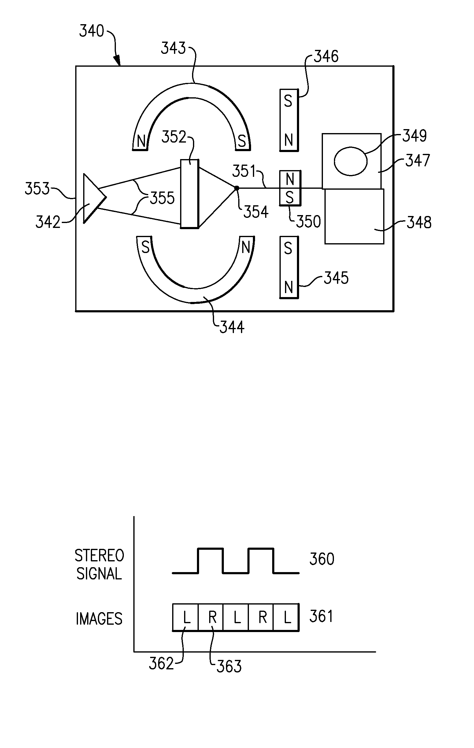
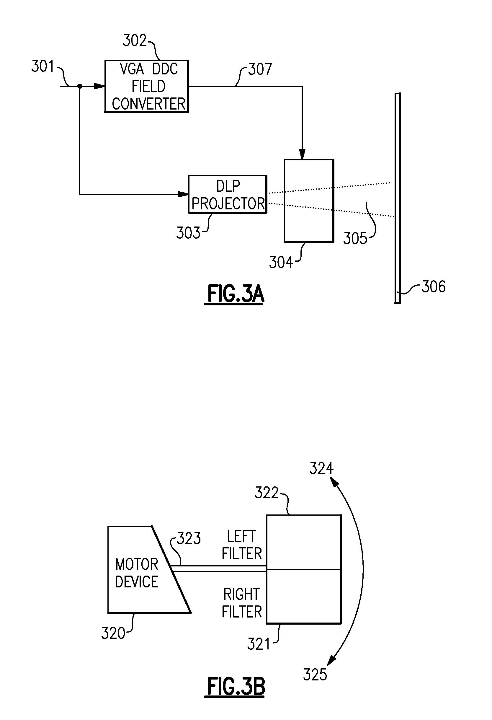
[0041]The present invention provides 3D viewing using passive eyewear, thus reducing cost and avoiding eye strain and color perception issues associated with various alternatives. It can be used with a single projection source based on popular DLP technology (or related technologies including GLV), and may be realized as either an integral part of a projection system or as an add-on peripheral or stand that can be placed in front of a projector. This invention takes advantage of the prior art 3D interface support provided in popular software packages, such as the OpenGL™ or Direct3D™ application programming interface (“API”), which includes variants such as java3D™. This interface is compatible with the vast majority of 3D image software and programs in use today. All of these APIs generate digital content with left / right eye perspectives, for use with alternative technologies such as the active shutter glasses described previously. This content can be used without modifications by ...


PUM


Abstract

An apparatus and method for stereoscopic 3D image projection and viewing using a single projection source, alternating polarization, and passive eyewear. This approach is applicable to frame sequential video created using existing 3D graphics APIs, as well as other video signal formats, and is compatible with existing digital light processor (DLP) technology for both front and rear projection systems. An alternating polarizer filter actuator in the form of a closed feedback loop is used to modulate the projected image. A preferred embodiment enables an existing DLP projection system to be enhanced with 3D capability.

Description

CROSS REFERENCES TO RELATED APPLICATIONS[0001]U.S. patent application Ser. No. 11 / 314,379, filed Dec. 21, 2005, entitled “STEREOGRAPHIC PROJECTION APPARATUS WITH PASSIVE EYEWEAR UTILIZING A CONTINUOUSLY VARIABLE POLARIZING ELEMENT”; Ser. No. ______, filed concurrently herewith, entitled “STEREOGRAPHIC IMAGING SYSTEM USING OPEN LOOP MAGNETOMECHANICALLY RESONANT POLARIZING FILTER ACTUATOR”; and Ser. No. ______, filed concurrently herewith, entitled “DYNAMIC PROJECTOR REFRESH RATE ADJUSTMENT VIA PWM CONTROL” are assigned to the same assignee hereof and contain subject matter related, in certain respect, to the subject matter of the present application. The above-identified patent applications are incorporated herein by reference in their entirety.BACKGROUND OF THE INVENTION[0002]1. Technical Field of the Invention[0003]The present invention provides a three dimensional (“3D”) image projection apparatus that can be combined with a single light source projection system, and enables a vie...

Claims


Application Information

Patent Timeline
Patent Type & Authority Applications(United States)
IPC IPC(8): H04N13/04H04N13/337H04N13/363
CPCG02B27/2228G02B27/26H04N13/0497H04N13/0459H04N13/0434H04N13/337H04N13/363H04N13/398G02B30/34G02B30/25
Inventor DECUSATIS, CASIMER M.TRIFILO, TIMOTHY M.
Owner IBM CORP
Learn More