Image stabilization mechanism and image pickup apparatus

a technology of image stabilization mechanism and image pickup, which is applied in the direction of printers, instruments, cameras focusing arrangements, etc., can solve the problems of difficult to reduce the size of the image stabilization mechanism, increase manufacturing costs, and complicated structure, and achieves reduced manufacturing costs, high precision, and reduced structure.

Inactive Publication Date: 2008-03-06
SONY CORP
View PDF8 Cites 13 Cited by
  • Summary
  • Abstract
  • Description
  • Claims
  • Application Information

AI Technical Summary

Benefits of technology

[0016]According to the present invention, in an image stabilization mechanism, a support member that supports a movable lens or an image sensor is directly supported by a base member. Thus, the structure is significantly simplified. Accordingly, the structure can be produced with high precision, yet low cost. In addition, an anti-rolling member is secured to or slidably mounted to a guide shaft and is slidably engaged with the support member or the base member. The anti-rolling member prevents rolling of the image stabilization mechanism. Therefore, rolling can be prevented using the significantly simplified structure.

Problems solved by technology

It follows that the structure is complicated and the manufacturing cost is increased.
In addition, it is difficult to reduce the size of the image stabilization mechanism.
Furthermore, since the number of components increases, it is difficult to provide a high positional precision.
As a result, mounting of a sensor (including position setting of the sensor) requires a large amount of time, and therefore, the manufacturing cost is further increased.
However, it is difficult to prevent rolling of the movable frame, that is, the rolling of the movable frame in a plane perpendicular to the light axis.

Method used


Image

  • Image stabilization mechanism and image pickup apparatus
  • Image stabilization mechanism and image pickup apparatus
  • Image stabilization mechanism and image pickup apparatus

Examples


first exemplary embodiment

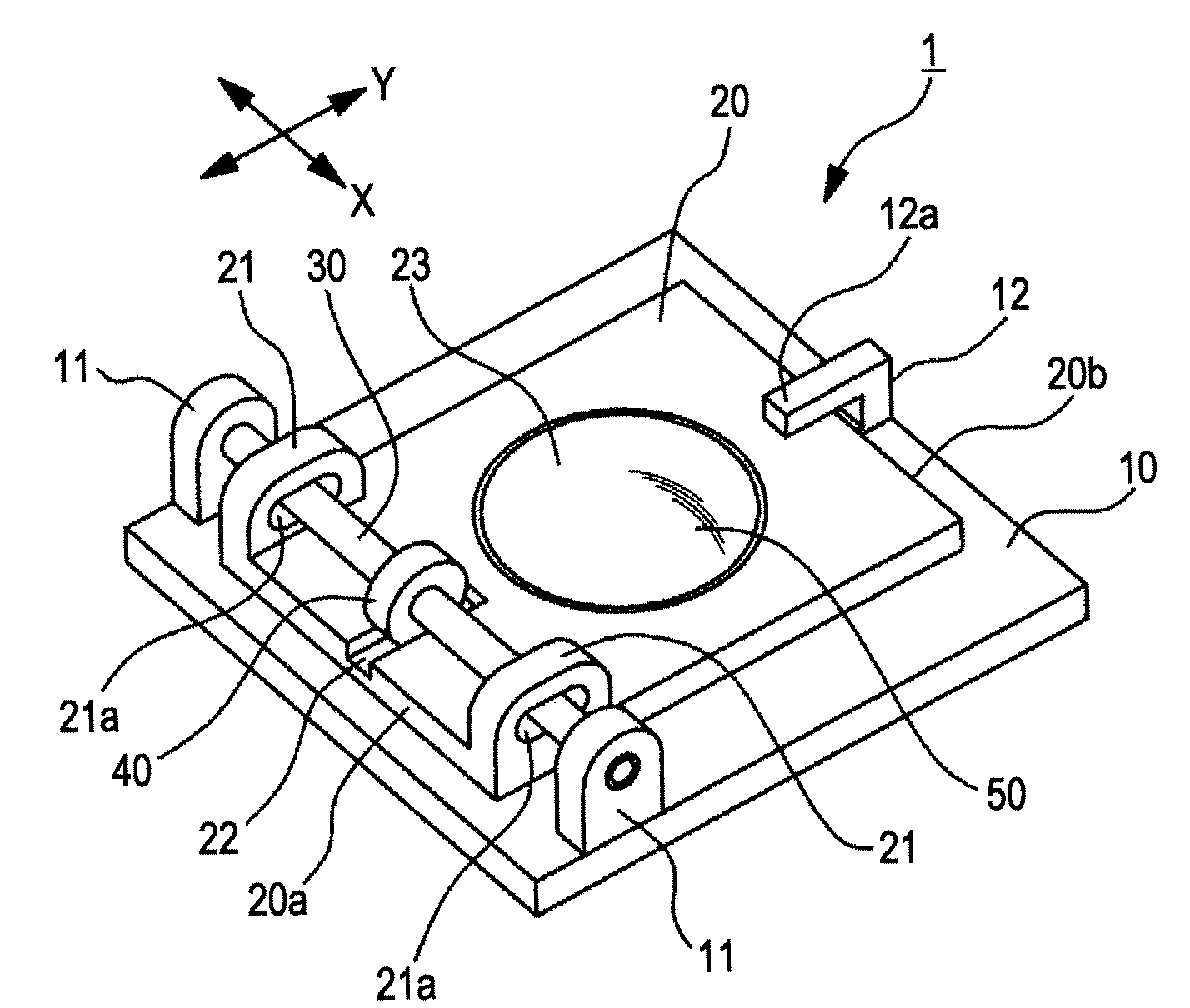
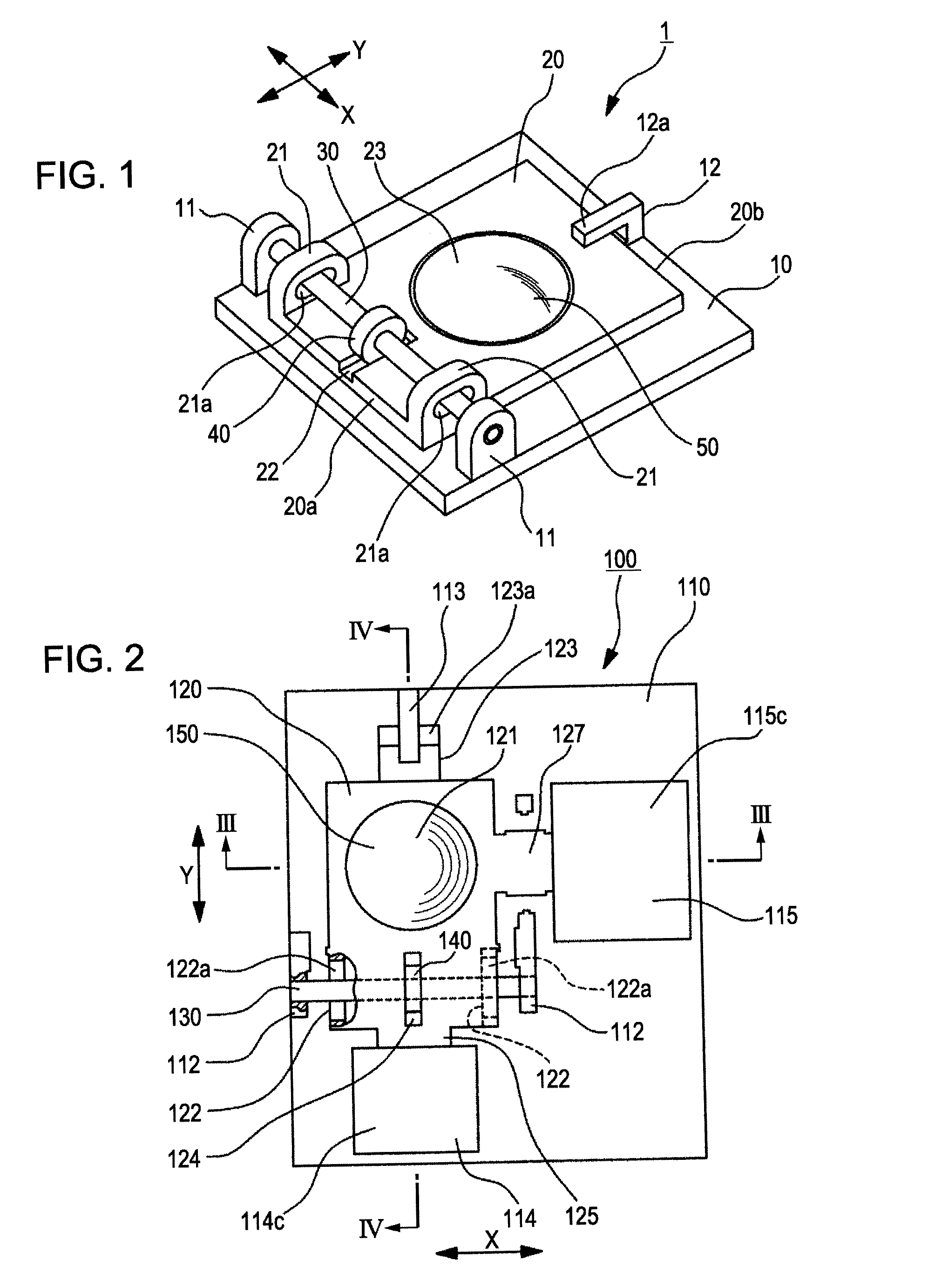
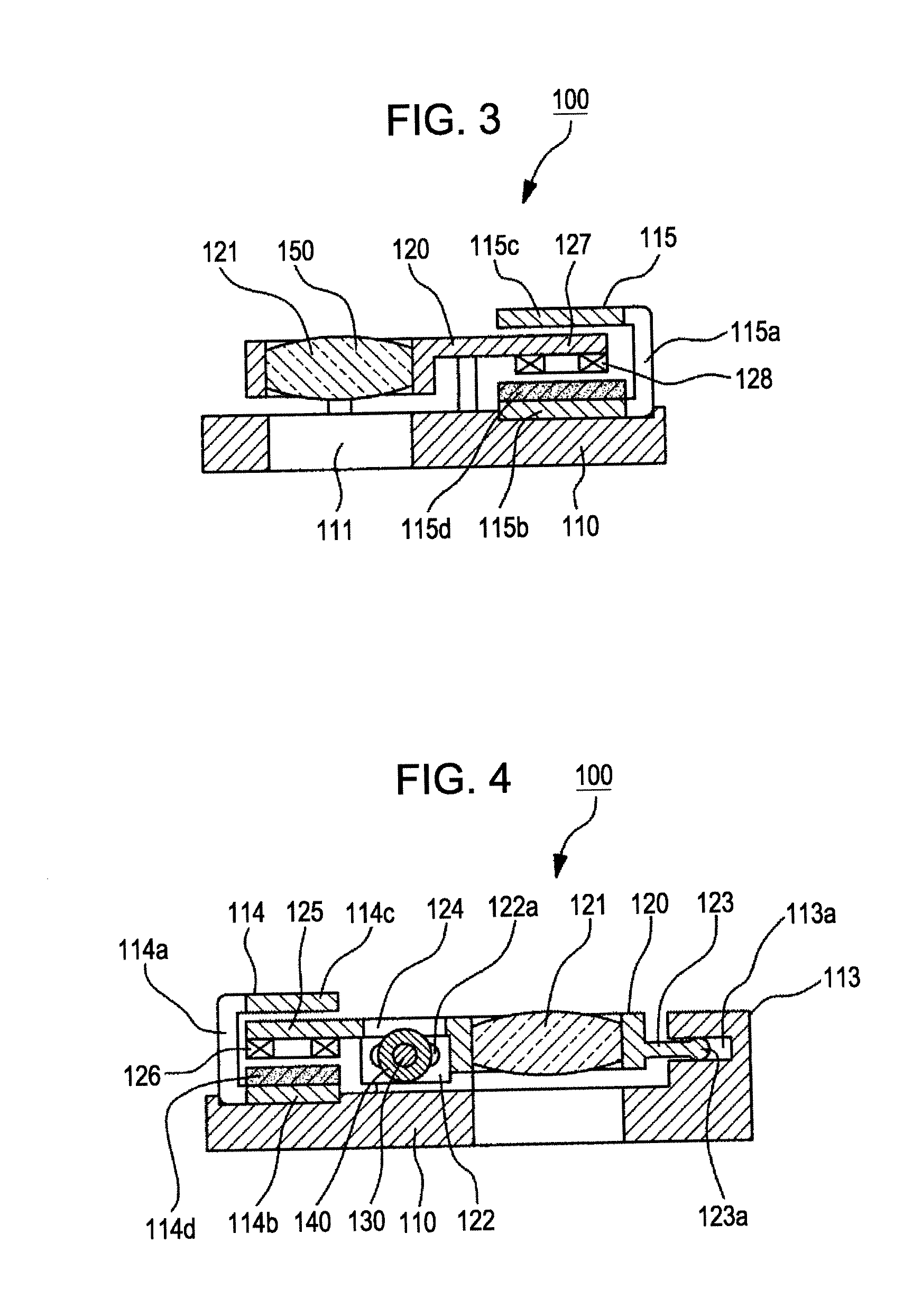
[0057]FIGS. 2 to 4 illustrate an image stabilization mechanism according to a first exemplary embodiment.

[0058]In the first exemplary embodiment and the following second to fourth embodiments, which are described below, the above-described image stabilization mechanism that moves a movable lens of an image-capturing lens system is employed. However, the image stabilization mechanism can be used for shifting an image sensor.

[0059]As shown in FIGS. 2 to 4, the image stabilization mechanism of the first exemplary embodiment includes a support member for supporting a movable lens or an image sensor, a base member, a guide shaft secured to the base member and extending in a first direction that is perpendicular to a second direction, an anti-rolling member, and two driving units for moving the support member independently in the first and second directions. The guide shaft passes through an elongate hole formed in the support member and is disposed in the elongate hole in a slidable mann...

second exemplary embodiment

[0075]FIGS. 6 to 8 illustrate an image stabilization mechanism according to a second exemplary embodiment of the present invention.

[0076]As shown in FIGS. 6 to 8, the image stabilization mechanism of the second exemplary embodiment includes a support member for supporting a movable lens or an image sensor, a base member, a guide shaft that extends in the first direction and is secured to the support member, an anti-rolling member that is fitted into the guide shaft in a slidable manner in the axis direction of the guide shaft, and two driving units for moving the support member independently in the first and second directions. The guide shaft passes through an elongate hole formed in the base member and is disposed in the elongate hole in a slidable manner in the first direction and a second direction that is perpendicular to the first direction. The anti-rolling member is engaged with the base member in a slidable manner in the second direction so as to prevent the support member f...

third exemplary embodiment

[0087]FIGS. 9 to 11 illustrate an image stabilization mechanism according to a third exemplary embodiment of the present invention.

[0088]As shown in FIGS. 9 to 11, the image stabilization mechanism of the third exemplary embodiment includes a support member for supporting a movable lens or an image sensor, a base member, a guide shaft that is supported by the base member in a slidable manner in the first direction and that is engaged with an elongate hole formed in the base member in a slidable manner in the second direction, an anti-rolling member that is secured to the guide shaft and that is engaged with the support member in a slidable manner in the second direction so as to prevent the support member from rotating about the light axis or the incident light axis, and two driving units for moving the support member independently in the first and second directions.

[0089]An image stabilization mechanism 300 includes a base member 310 and a support member 320 supported by the base m...


PUM


Abstract

An image stabilization mechanism moves a movable lens or an imager in first and second directions perpendicular to each other and perpendicular to a light axis of the lens or an incident light axis of the imager. The mechanism includes a support member for supporting the movable lens or imager, a base member, a guide shaft secured to the base member and extending in the first direction, where the guide shaft is disposed in an elongate hole formed in the support member in a slidable manner in the first and second directions, an anti-rolling member fitted into the guide shaft in a slidable manner in its axis direction and engaged with the support member in a slidable manner in the second direction so as to prevent rolling of the support member about the light axis, and two drivers for moving the support member independently in the first and second directions.

Description

CROSS REFERENCES TO RELATED APPLICATIONS[0001]The present invention contains subject matter related to Japanese Patent Application JP 2006-239993 filed in the Japanese Patent Office on Sep. 5, 2006, the entire contents of which are incorporated herein by reference.BACKGROUND OF THE INVENTION[0002]1. Field of the Invention[0003]The present invention relates to an image stabilization mechanism and an image pickup apparatus and, in particular, to technology that produces a compact image stabilization mechanism capable of moving in a plane in two directions perpendicular to each other without rolling thereof and with a small number of components thereof.[0004]2. Description of the Related Art[0005]Some image pickup apparatuses (e.g., video cameras, still image cameras, or camera units incorporated in portable electronic devices, such as cell phones) include an image stabilization mechanism. The image stabilization mechanism compensates for image blurring caused by camera shake occurring...

Claims


Application Information

Patent Timeline
Patent Type & Authority Applications(United States)
IPC IPC(8): G03B3/00
CPCG02B27/646H04N5/23287H04N5/23248H04N23/68H04N23/687
Inventor MAKII, TATSUO
Owner SONY CORP
Why Eureka
Try Eureka