Optical scanning device and image forming apparatus

Inactive Publication Date: 2008-03-06
RICOH KK
View PDF21 Cites 44 Cited by
  • Summary
  • Abstract
  • Description
  • Claims
  • Application Information

AI Technical Summary

Benefits of technology

[0011]It is an object of the present invention to at least

Problems solved by technology

However, in the method (1), there are problems in that because the elements are mounted in a plurality of numbers, a light source unit becomes complicated, the number of parts increases and complicated adjustment is required.
In the method (2), there is a problem that there is a difference in wavelength between the light emitting units, and individual adjustment is not possible.
However, because the diffraction plane is very sensitive to a difference in wav

Method used


Image

  • Optical scanning device and image forming apparatus
  • Optical scanning device and image forming apparatus
  • Optical scanning device and image forming apparatus

Examples


Example

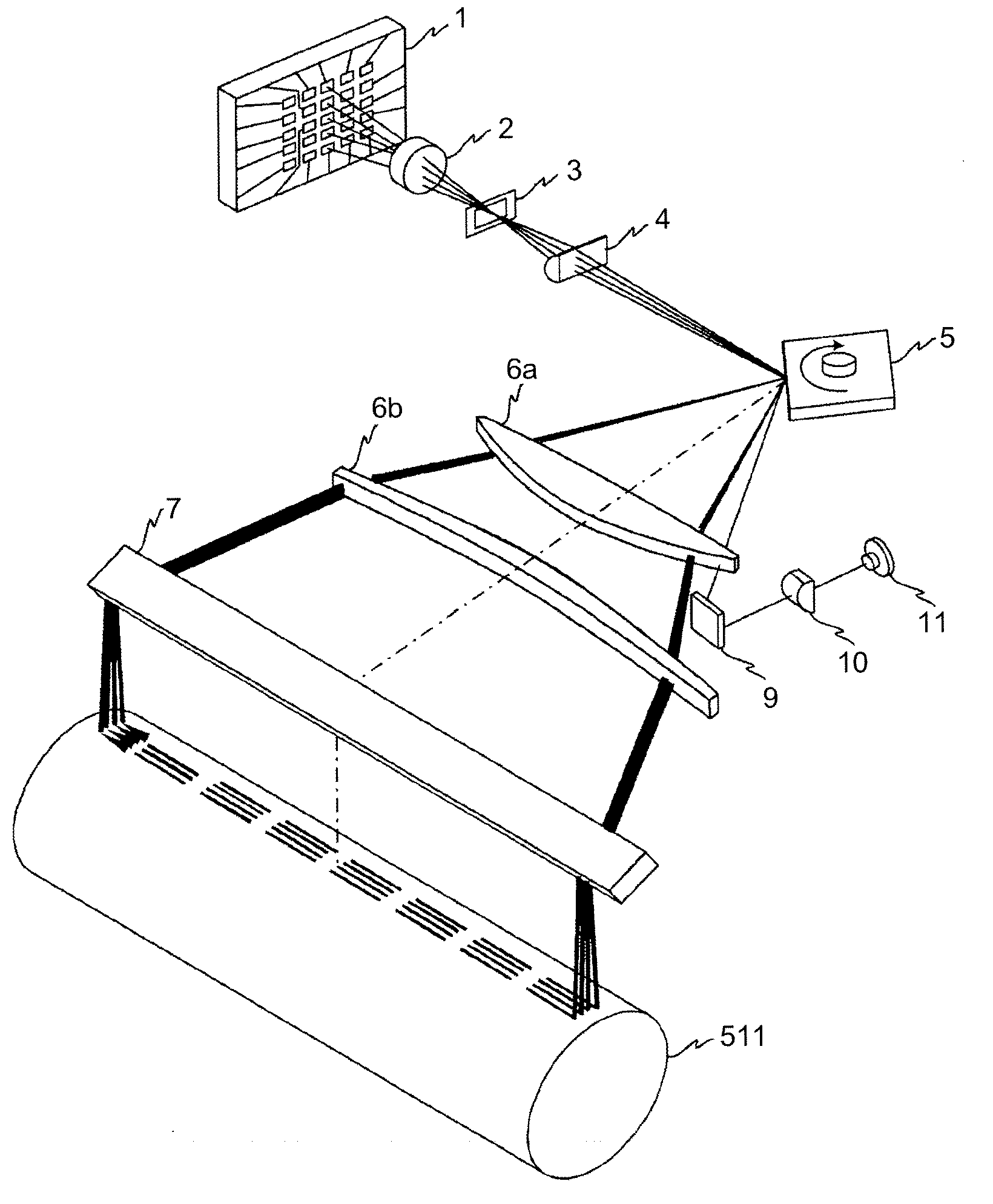
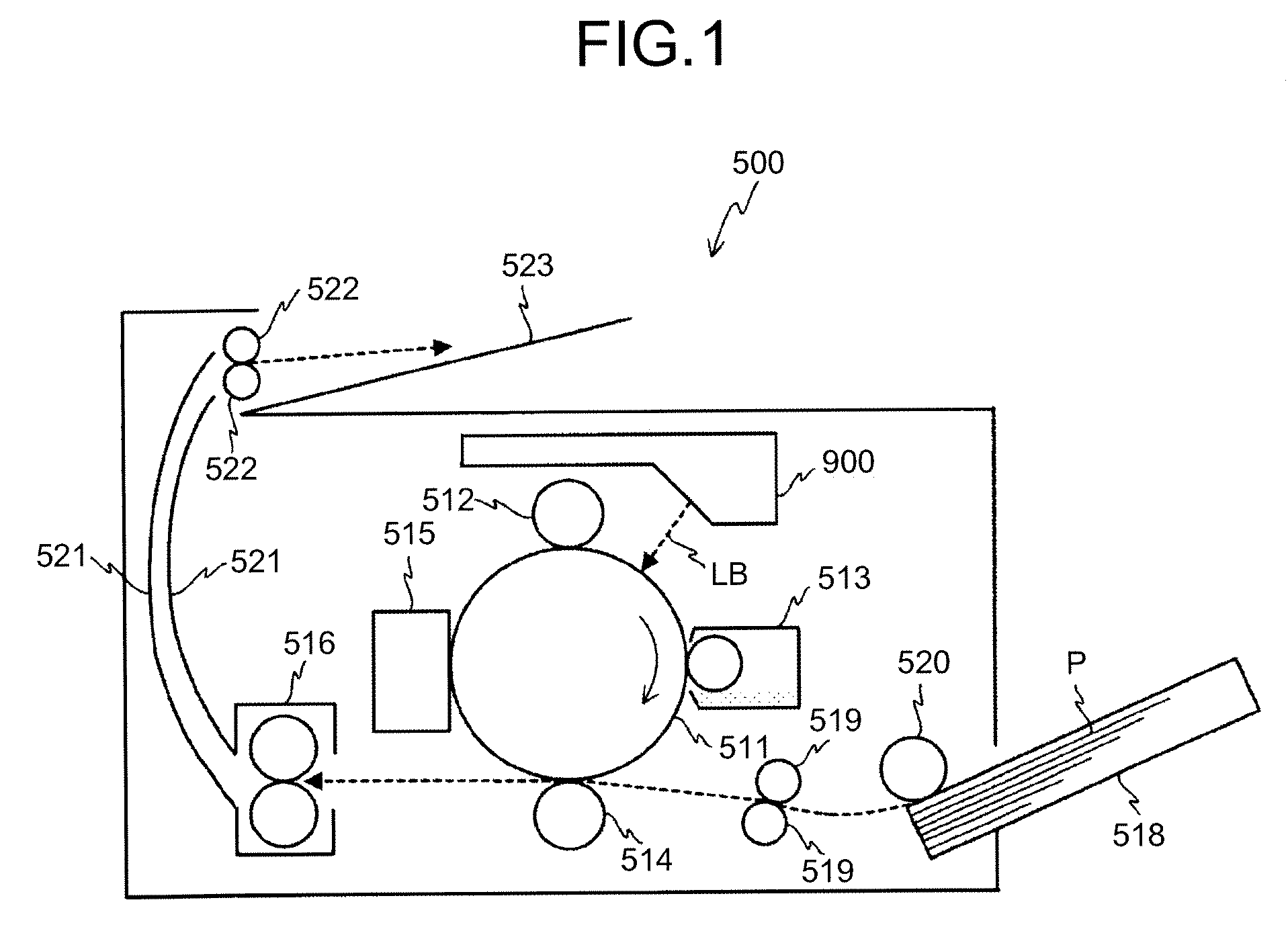
[0027]Exemplary embodiments of the present invention are explained in detail below with reference to the accompanying drawings. FIG. 1 is a schematic diagram for explaining a configuration of a laser printer 500 as an image forming apparatus according to an embodiment of the present invention.

[0028]The laser printer 500 includes a photoconductive drum 511, a charging roller 512, a developing unit 513, a transfer roller 514, a cleaning unit 515, a fuser 516, an optical scanning device 900, a cartridge 518, a registration roller pair 519, a paper feed roller 520, a pair of paper ejection rollers 522, and a tray 523.

[0029]The charging roller 512, the developing unit 513, the transfer roller 514, and the cleaning unit 515 are respectively arranged near the surface of the photoconductive drum 511. These units are arranged along the rotation direction of the photoconductive drum 511 (a direction of arrow in FIG. 1) in an order of the charging roller 512, the developing unit 513, the trans...


PUM


Abstract

A coupling lens arranged on an optical path of an optical beam from a VCSEL, which has a refraction plane and a diffraction plane that respectively change a power according to a temperature change and suppresses a beam-waist position change in a main-scanning direction and a sub-scanning directions on the scanning surface caused by the temperature change, by a wavelength change of the optical beam caused by power changes of the refraction plane and the diffraction plane and the temperature change. A deflecting unit deflects the optical beam that passed through the coupling lens. A scanning optical system condenses a deflected optical beam on the scanning surface.

Description

CROSS-REFERENCE TO RELATED APPLICATIONS[0001]The present application claims priority to and incorporates by reference the entire contents of Japanese priority document, 2006-239564 filed in Japan on Sep. 4, 2006.BACKGROUND OF THE INVENTION[0002]1. Field of the Invention[0003]The present invention relates to an optical scanning device and an image forming apparatus, and, more particularly to an optical scanning device that scans a scanning surface by beams from a light source, and to an image forming apparatus including the optical scanning device.[0004]2. Description of the Related Art[0005]Recently, high stability relative to temperature change, high definition (high image quality), and high speed as well as cost reduction are required for image forming apparatuses such as an optical printer, a digital copying machine, and an optical plotter. These image forming apparatuses generally include an optical scanning device that scans a scanning surface by beams from a light source.[0006...

Claims


Application Information

Patent Timeline
IPC IPC(8): G02B26/10G02F1/00
CPCG02B5/1876G02B26/124H04N1/1135H04N2201/04744H04N2201/04729H04N2201/04732H04N2201/0471
Inventor SAISHO, KENICHIROHHAYASHI, YOSHINORIUEDA, TAKESHISAKAI, KOHJIICHII, DAISUKE
Owner RICOH KK
Why Eureka
Try Eureka