Time counting assembly with a display for world time zones

a time counting and assembly technology, applied in the field of time counting assembly, can solve the problems of simple world time clocks, not meeting human engineering criterion, and dials that appear too complicated, and achieve the effect of low profile features

Inactive Publication Date: 2008-03-06
ATOP PRECISION IND CO LTD
View PDF6 Cites 18 Cited by
  • Summary
  • Abstract
  • Description
  • Claims
  • Application Information

AI Technical Summary

Benefits of technology

[0007] The present invention has been accomplished under the circumstances in view. It is therefore the main object of the present invention to provide a time counting assembly with a display for world time zones, which has a low profile feature with world time zone display and adjustable functions suitable for use in a watch,

Problems solved by technology

The deficiency involved in the conventional world time clock is that the dial appears too much complicated and it does not fulfill the criterion of human engineering from the standpoint of vision cognition and transmission.
However, the simple type of world time clock is also involved in a defect that the movement has to provide a 24-hour display.
Moreover, the time zone ring is easily loosened after using a period of time caused by no locating device available for the time zone ring being steadily attached to the dial such that it may result in a difficulty of reading the time.
Besides, the time zone ring on the simple type of world time clock is disposed to have a distance from the 24-hour graduation on the dial so that it is easy to occur a reading error.
Furthermore, the dial has to be arranged with 24 graduations standing for 24 hours and the gap between two neighboring hour graduations is reduced in a limited space such that it is unfavorable for the reading of minute hand and it is not possible for the alarm being aligned accurately.

Method used


Image

  • Time counting assembly with a display for world time zones
  • Time counting assembly with a display for world time zones
  • Time counting assembly with a display for world time zones

Examples


Embodiment Construction

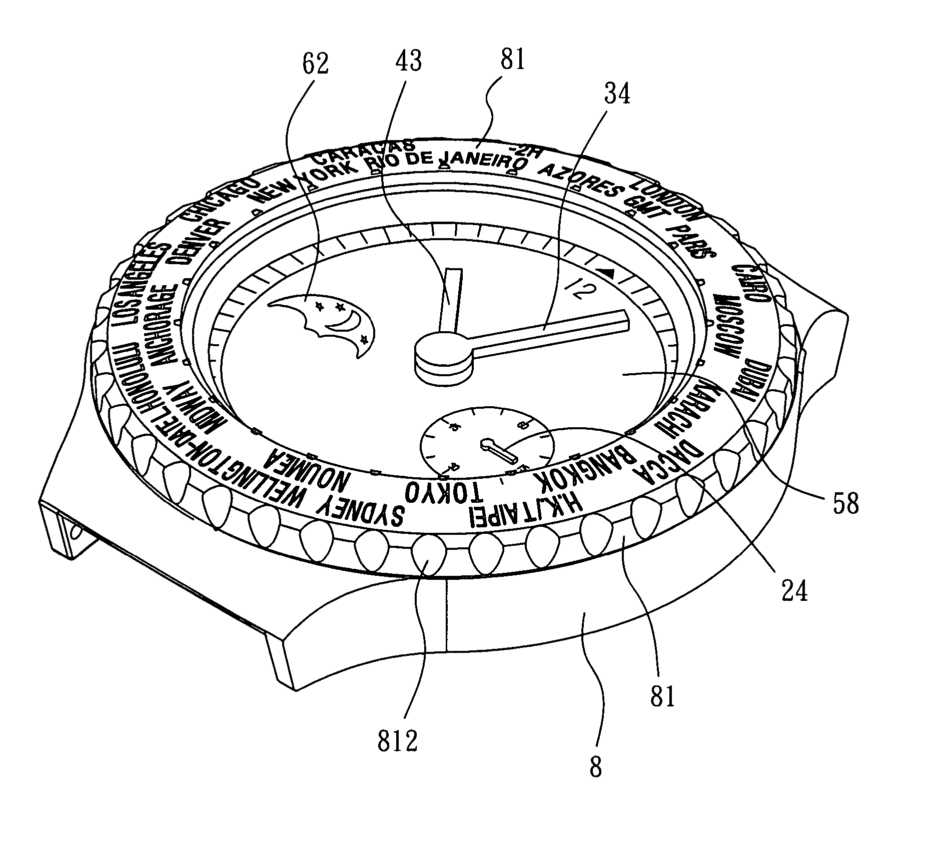
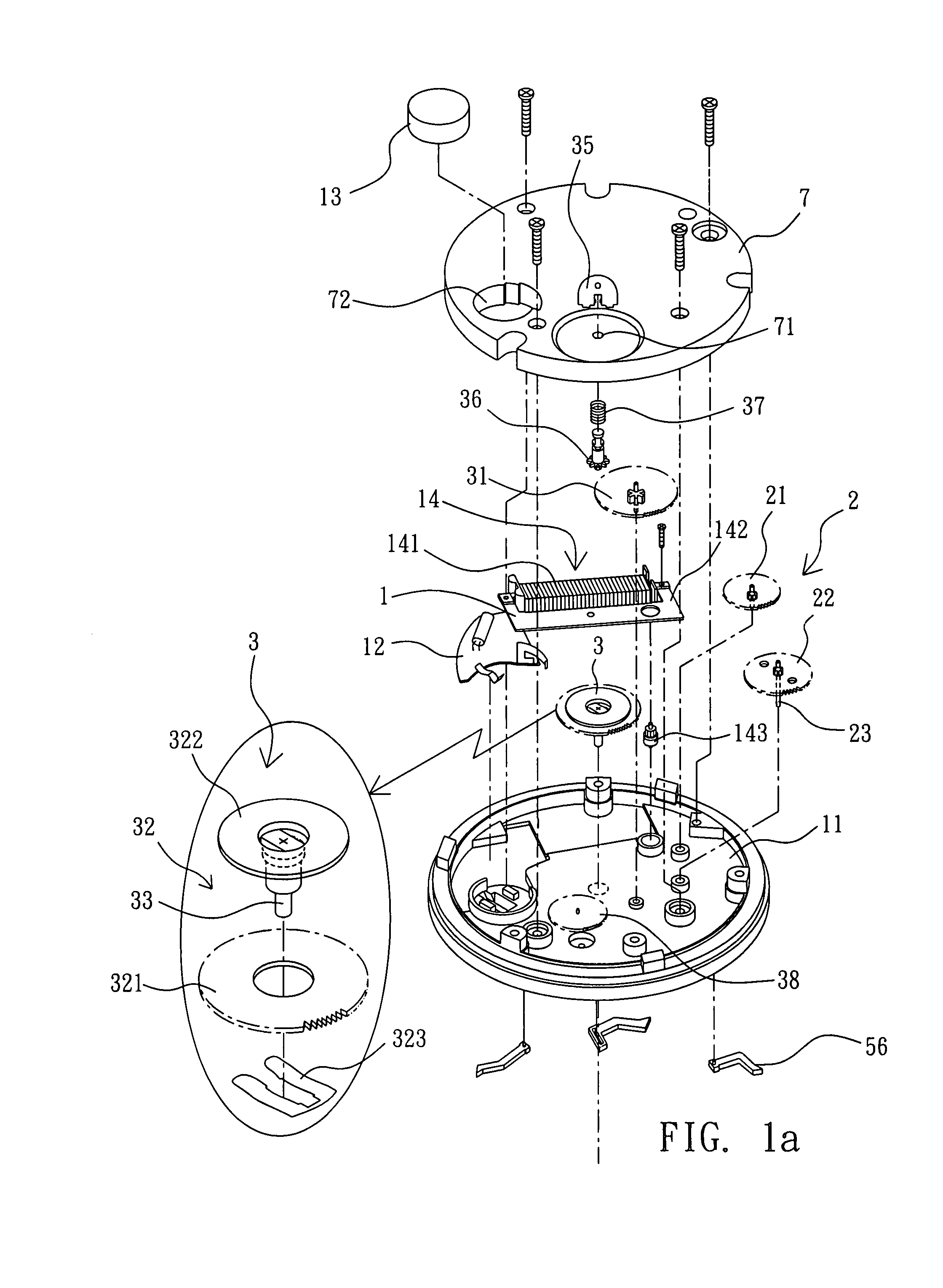
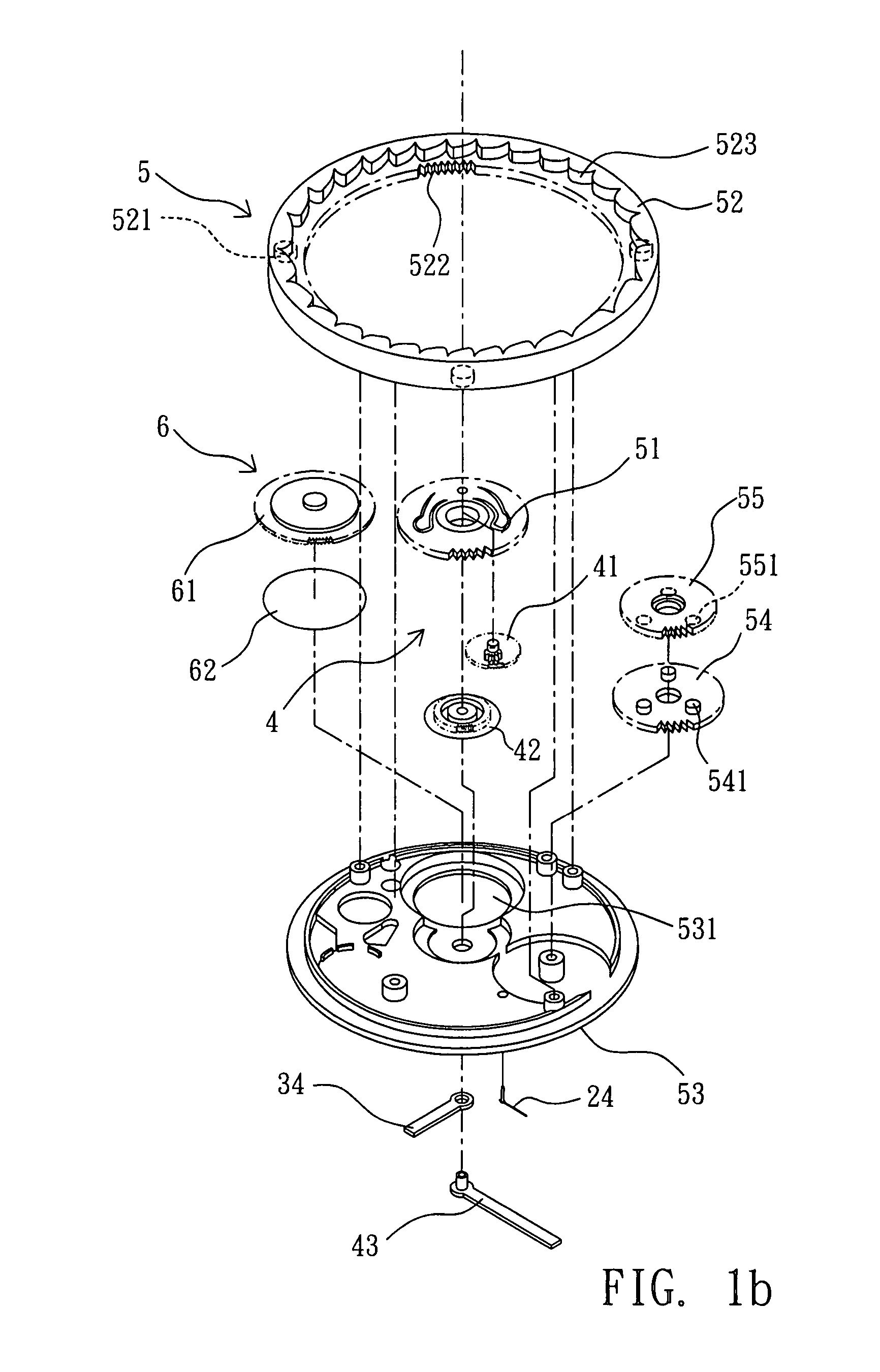
[0023] Referring to FIGS. 1a to 6, a time counting assembly with a display for world time zones according to the present invention basically comprises a power source 1, a second counter 2, a minute counter 3, an hour counter 4, and a time zone display 5. In addition, the time counting assembly of the present invention further comprises a day-night display 6.

[0024] The power source 1 is disposed above a substrate 11 and a circuit board 12, and the power source 1 provides a battery 13 mounted to the circuit board 12. Thus, the power can be supplied to a conventional stepping motor 14 composed of a coil 141, stator 142, and a rotor 143 so that the rotor 143 can rotate with a constant speed to transmit the power to the second counter 2.

[0025] The second counter 2 provides a front second wheel 21 is axially attached to the substrate 11 and meshes with the rotor 143 so as to be driven by the rotor 143. The front second wheel 21 further meshes with a second wheel 22 so that a second spin...


PUM


Abstract

A time counting assembly with a display for world time zones comprised of a power source, a second counter, a minute counter, an hour counter, and a time zone display for displaying a correct time over a faceplate. Stir the time zone adjustable ring with the hand to align a first landmark of a local time zone with a fixed point and then calibrate the time counting assembly in accordance with the local time, and then stir the time zone adjustable ring with the hand to align a second landmark of another locating time zone with the fixed point such that the inner gear ring moves the planetary idle gear set and the planetary base wheel to shift engagement of the engaging hooks in the ratchet holes, and the front hour wheel is rotated on the planetary base wheel with a planetary movement along the minute wheel set to cause rotation of a meshed hour wheel so as to turn a hour hand to the time in accordance with the time zone corresponding to the second landmark. The direct time zone adjustment design greatly reduces the thickness of the assembly so that the time counting assembly is usable in a watch or low-profile timer while maintaining world time zone display and adjustable functions, and providing a modularized design function for ultra-thin time recording device.

Description

BACKGROUND OF THE INVENTION [0001] 1.Field of the Invention [0002] The present invention relates to a time counting assembly, and particularly to a time counting assembly with a display for world time zones. [0003] 2.Description of Related Art [0004] It is known that the international exchange is getting more frequent and the transnational contact is getting popular due to the advance of the traffic and communication. In order to consider the factor with regard to the transmission of information and to the time difference, a clock possible to show the time of any other zone, or the so-called world time clock is developed to respond the necessity. [0005] Mostly, a conventional world time clock at the dial thereof is printed with a world map and a local time is looked up in the world map. The deficiency involved in the conventional world time clock is that the dial appears too much complicated and it does not fulfill the criterion of human engineering from the standpoint of vision cog...

Claims


Application Information

Patent Timeline
Patent Type & Authority Applications(United States)
IPC IPC(8): G04B19/22
CPCG04G9/0076G04B19/22G04B19/223
Inventor LIN, WEN-CHUN
Owner ATOP PRECISION IND CO LTD
Why Eureka
Try Eureka