Pedometer

Inactive Publication Date: 2008-03-06
SEIKO INSTR INC
View PDF3 Cites 16 Cited by
  • Summary
  • Abstract
  • Description
  • Claims
  • Application Information

AI Technical Summary

Benefits of technology

[0021]According to the pedometer of the invention, more correct step counting is possible to perform while suppressing element-based variations and individual difference effect.
[0022]Meanwhile, because the walking pitch upon sensitivity adjustment is not structurally regulated at a particular one type of value, ad

Problems solved by technology

However, with the above pedometer, in the case the notification period is not matched to the walk period the user is accustomed to, the user is obliged to walk in a different way from his/her usual walking, t

Method used


Image

  • Pedometer
  • Pedometer
  • Pedometer

Examples


first embodiment

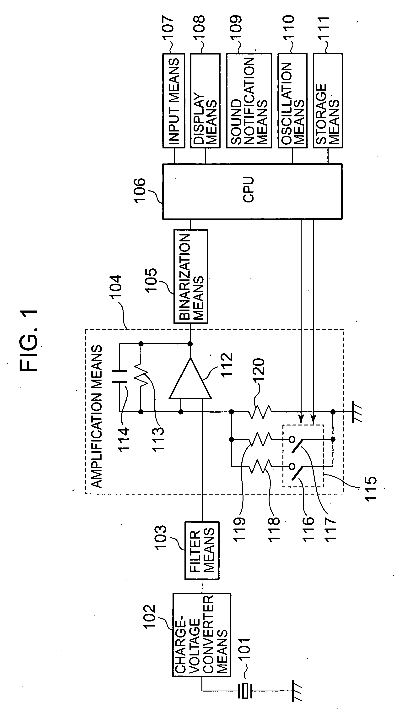
[0028]FIG. 1 is a block diagram of a pedometer according to the present invention, illustrating an example of a pedometer structured to be used by being carried in a state worn on the wrist or waste or put accommodated in a bag or the like.

[0029]In FIG. 1, the pedometer has an acceleration sensor 101 that detects a walk (including a run) of the user and outputs a charge signal (walk signal) corresponding to the walk, charge-voltage converting means 102 that converts the charge walk signal of from the acceleration sensor 101 into the corresponding voltage walk signal to output, filter means 103 that outputs a walk signal removed of noise from the output signal of from the charge-voltage converting means 102, amplification means 104 that amplifies and outputs the walk signal of from the filter means 103, and binarization means 105 that waveform-shapes the walk signal of from the amplification means 104 and outputs a walk signal in the form of a binary digital signal. Incidentally, the...

second embodiment

[0058]FIG. 4 is a block diagram of a pedometer according to the invention, wherein like reference numeral is attached to like element of FIG. 1.

[0059]Although the first embodiment was arranged to adjust the gain of the amplification means 104 in order to adjust the sensitivity of the walk detecting means, the second embodiment is configured to adjust / control the gain of the charge-voltage converting means.

[0060]In FIG. 4, the pedometer has an acceleration sensor 101 that detects a walk (including a run) of the user and outputs a charge signal (walk signal) corresponding to the walk, charge-voltage converting means 401 that converts the charge walk signal from the acceleration sensor 101 into a corresponding voltage walk signal to output, filter means 103 that removes noise from the signal of from the charge-voltage converting means 401 and outputs a walk signal, amplification means 402 that amplifies and outputs the walk signal of from the filter means 103, and binarization means 10...


PUM


Abstract

An acceleration sensor outputs a walk signal having a charge corresponding to a walk. The walk signal is converted by charge-voltage conversion means into a voltage walk signal, removed of noise by filter means, amplified by amplification means and converted by binarization means into a digital signal, followed by being inputted to a CPU. The CPU performs open-close control of switches, such that the walking pitch, calculated based on the walk signal, comes within a predetermined walking pitch range stored in the storage means thereby controlling the gain of the amplification means and controlling the walk detection sensitivity properly.

Description

BACKGROUND OF THE INVENTION[0001]1. Field of the Invention[0002]The present invention relates to a pedometer that detects walking and takes count of walk steps.[0003]2. Description of the Related Art[0004]Conventionally, development has been made for a pedometer for taking walk steps of a user by being used in the state worn on the body, such as the wrist or the waste, of the user or put in a bag the user carries. Devising is made variously for the pedometer in order to correctly take count of steps while suppressing the effects of body movement noises, etc.[0005]In the pedometer described in Patent document 1 described below for example, the user is notified with a predetermined period by notification means such as sound. Walk determination adjusting means is configured to adjust a determination criterion at the walk determining means so that a walk signal detected can be in synchronism with the notification period of the notification means. By properly adjusting at least one of a ...

Claims


Application Information

Patent Timeline
IPC IPC(8): G01C21/00
CPCG01C22/006
Inventor TSUBATA, KEISUKE
Owner SEIKO INSTR INC
Why Eureka
Try Eureka