Encapsulated and vented particulate thermal insulation

Active Publication Date: 2008-03-06
RAYTHEON CO +1
View PDF61 Cites 13 Cited by
  • Summary
  • Abstract
  • Description
  • Claims
  • Application Information

AI Technical Summary

Benefits of technology

[0015]The present material replaces MLI in space applications. The vented-envelope construction allows gases within the encapsulated insulation to escape during launch, and when exposed to the vacuum of space leaves the encapsulated insulation with an interior vacuum that prevents conductive heat loss. The particulate insulation prevents the envelope from collapsing in thickness during installation and service, avoiding thermal shorts. The particulate insulation, particularly the fiber-reinforced aerogel insulation, and the thin envelope material are sufficiently flexib

Problems solved by technology

Even slight temperature-induced deformation may cause a sensitive structure to become inoperable.
At higher temperatures, the devices may become inefficient or cease operation entirely.
The more heat that the refrigerator must remove, the larger it is and the more power it consumes.
Additionally, the more heat leakage, the slower the initial cool-down of the cooled device, and the greater the cooling capacity required to maintain the cooled device at the operating temperature.
This application is a slow, costly process.
The MLI may be effective in insulating the device, but it is extremely difficult and time-consuming to apply correctly.
As a result, even after careful application precisely following the es

Method used


Image

  • Encapsulated and vented particulate thermal insulation
  • Encapsulated and vented particulate thermal insulation
  • Encapsulated and vented particulate thermal insulation

Examples


Embodiment Construction

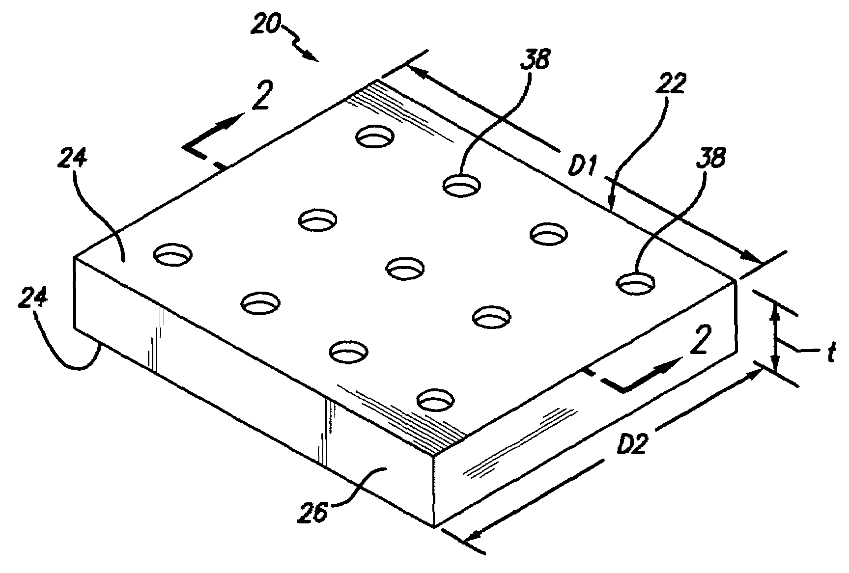
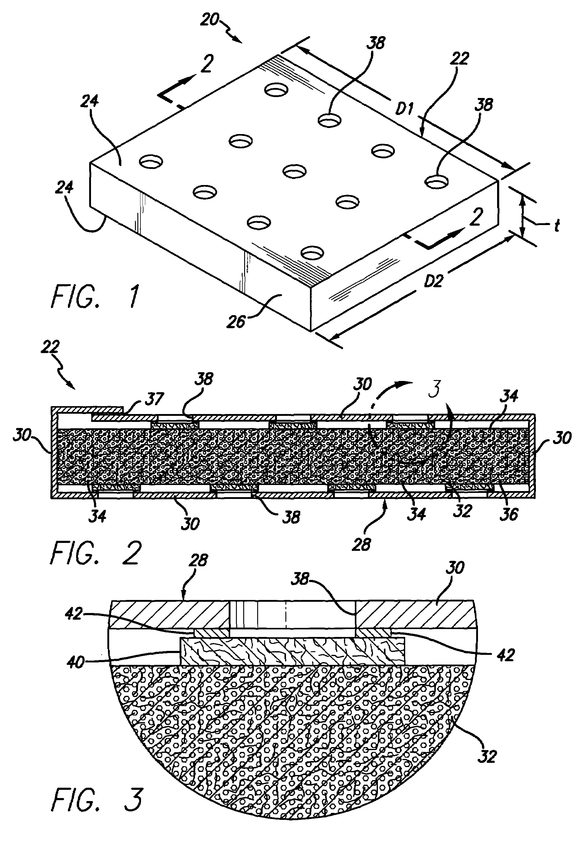
[0027]FIG. 1 depicts in perspective view an article 20 that includes a piece of encapsulated insulation 22. The piece of encapsulated insulation 22 preferably, but not necessarily, has a blanket shape with two substantially equal opposing faces 24, and an edge 26 separating the opposing faces 24. A surface area of the edge 26 is smaller than a surface area of either of the opposing faces. The edge separates the opposing faces 24 by a distance of from 0.08 to 0.75 inches, most preferably 0.25 inches, which defines the thickness of the blanket-shaped piece of encapsulated insulation 22. Typically, in such a blanket the transverse dimensions D1 and D2 of the faces 24 are much larger than the separation dimension or thickness t (i.e., at least 10 times, sometimes at least 20 times, and often 50 or more times larger than t) of the piece of encapsulated insulation 22. In another but substantially equivalent form of the piece of encapsulated insulation 22, the periphery of the opposing fac...


PUM

PropertyMeasurementUnit
Lengthaaaaaaaaaa
Lengthaaaaaaaaaa
Thicknessaaaaaaaaaa

Abstract

An article includes a piece of encapsulated insulation including an envelope having at least two vents therethrough, a particulate insulation within the envelope, and a porous filter overlying each vent of the envelope. The porous filter has a mesh size no larger that the minimum size of the particles. The article may further include a structure having a structure surface, and the piece of encapsulated insulation overlies and covers at least a portion of the structure surface.

Description

[0001]This invention relates to a thermal insulation material and its use and, more particularly, to the structure and use of a fiber-reinforced aerogel composite that is encapsulated and vented through porous filters that prevent the loss of particulate material to the environment.BACKGROUND OF THE INVENTION[0002]Temperature control is an important consideration in many spacecraft applications. In one spacecraft application, structures must be protected against temperature extremes of heat or cold that could cause the structure to warp or otherwise become damaged. Even slight temperature-induced deformation may cause a sensitive structure to become inoperable.[0003]In another spacecraft application, some devices must be maintained at extremely low operating temperatures. For example, many electronic components that process infrared signals are operated at cryogenic temperatures (e.g., 77 K or less) to avoid spurious heat-related signals or because the instrumentation functions prop...

Claims


Application Information

Patent Timeline
IPC IPC(8): B32B15/00B22F3/26B32B9/04
CPCC04B30/02C04B2111/00612C04B2111/28E04B1/80Y10T428/12007Y10T428/12493Y10T428/237C04B14/064Y10T428/31504Y10T428/249953
Inventor SCHROTH, ALBERTO E.CLARK, JIMMY L.DOAN, MICHAELLA KOMSKI, DAVID M.WHITE, SHANNON O.SMITH, STEPHEN E.SHAFFER, CHRISTOPHER M.KRONE-SCHMIDT, WILFRIED
Owner RAYTHEON CO
Why Eureka
Try Eureka