Hybrid vehicle control apparatus

a technology of vehicle control and hybrid vehicle, applied in mechanical devices, transportation and packaging, road transportation, etc., can solve the problem of unfavorable large response delay, and achieve the effect of eliminating physical shock resulting from gear shifting and simple shift control

Active Publication Date: 2008-03-06
NISSAN MOTOR CO LTD
View PDF3 Cites 64 Cited by
  • Summary
  • Abstract
  • Description
  • Claims
  • Application Information

AI Technical Summary

Benefits of technology

[0008]It has been discovered that in the automatic transmission used in the above mentioned hybrid vehicle, the automatic transmission is often provided with a gear in which power from the engine and / or the motor / generator is transmitted through a one-way clutch such that physical shock resulting from gear shifting can be eliminated with a simple shift control.
[0011]The present invention was conceived based on recognition of the fact that in the kind of hybrid vehicle described above, it is possible to control a rotational speed of the input side of the one-way clutch when the vehicle is coasting before an acceleration operation is performed by controlling the rotational speed of the motor / generator in such a fashion that power is not transmitted from the motor / generator to the wheels. One object of the present invention is to provide a hybrid vehicle control apparatus that can resolve the aforementioned problems of a long response delay and one-way clutch engagement shock by controlling the rotational speed of the motor / generator while the vehicle is coasting prior to re-acceleration.

Problems solved by technology

Consequently, an undesirably large response delay can occur between when the driver starts to accelerate with the one-way clutch being engaged again.

Method used


Image

  • Hybrid vehicle control apparatus
  • Hybrid vehicle control apparatus
  • Hybrid vehicle control apparatus

Examples


Embodiment Construction

[0028]Selected embodiments of the present invention will now be explained with reference to the drawings. It will be apparent to those skilled in the art from this disclosure that the following descriptions of the embodiments of the present invention are provided for illustration only and not for the purpose of limiting the invention as defined by the appended claims and their equivalents.

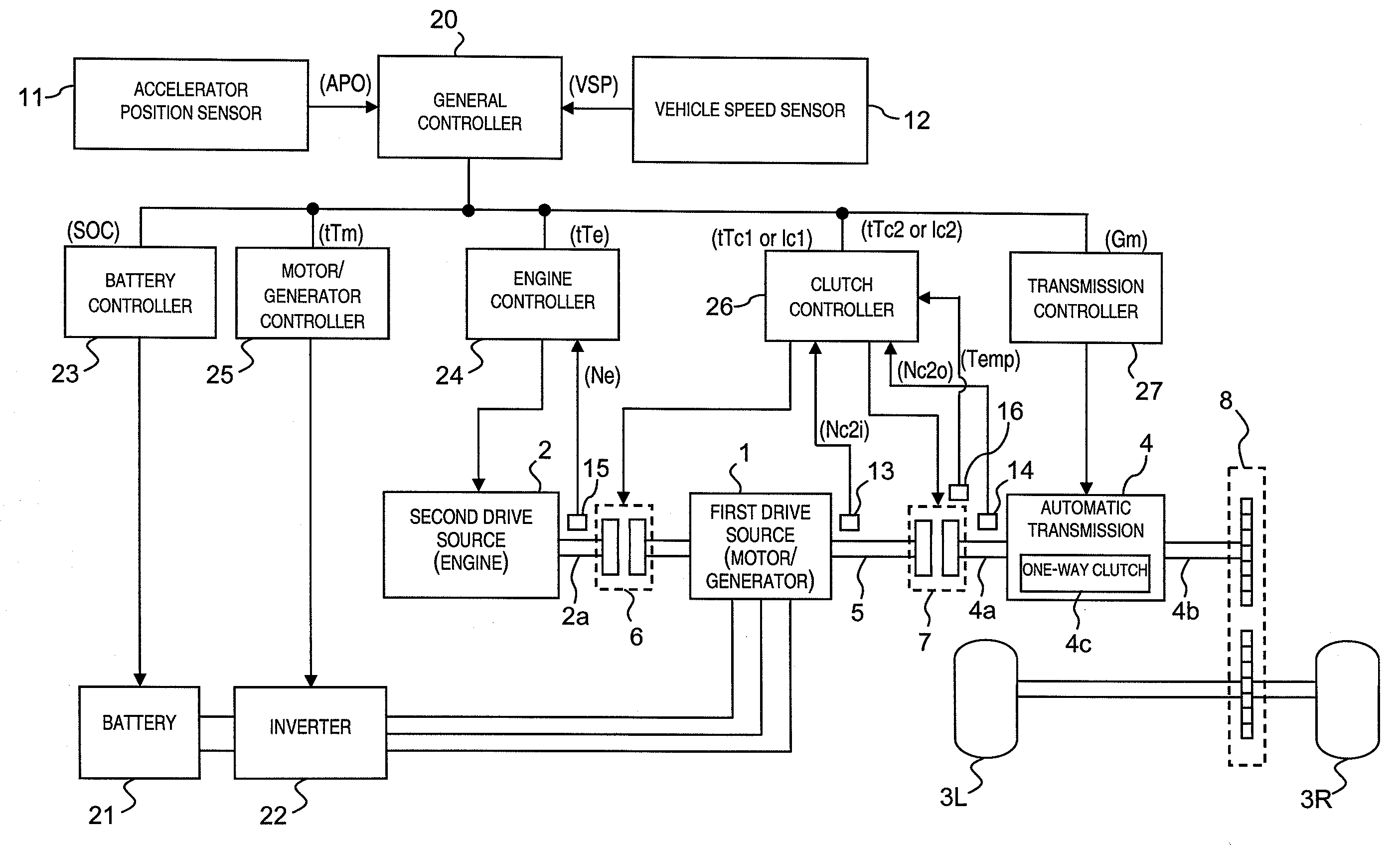
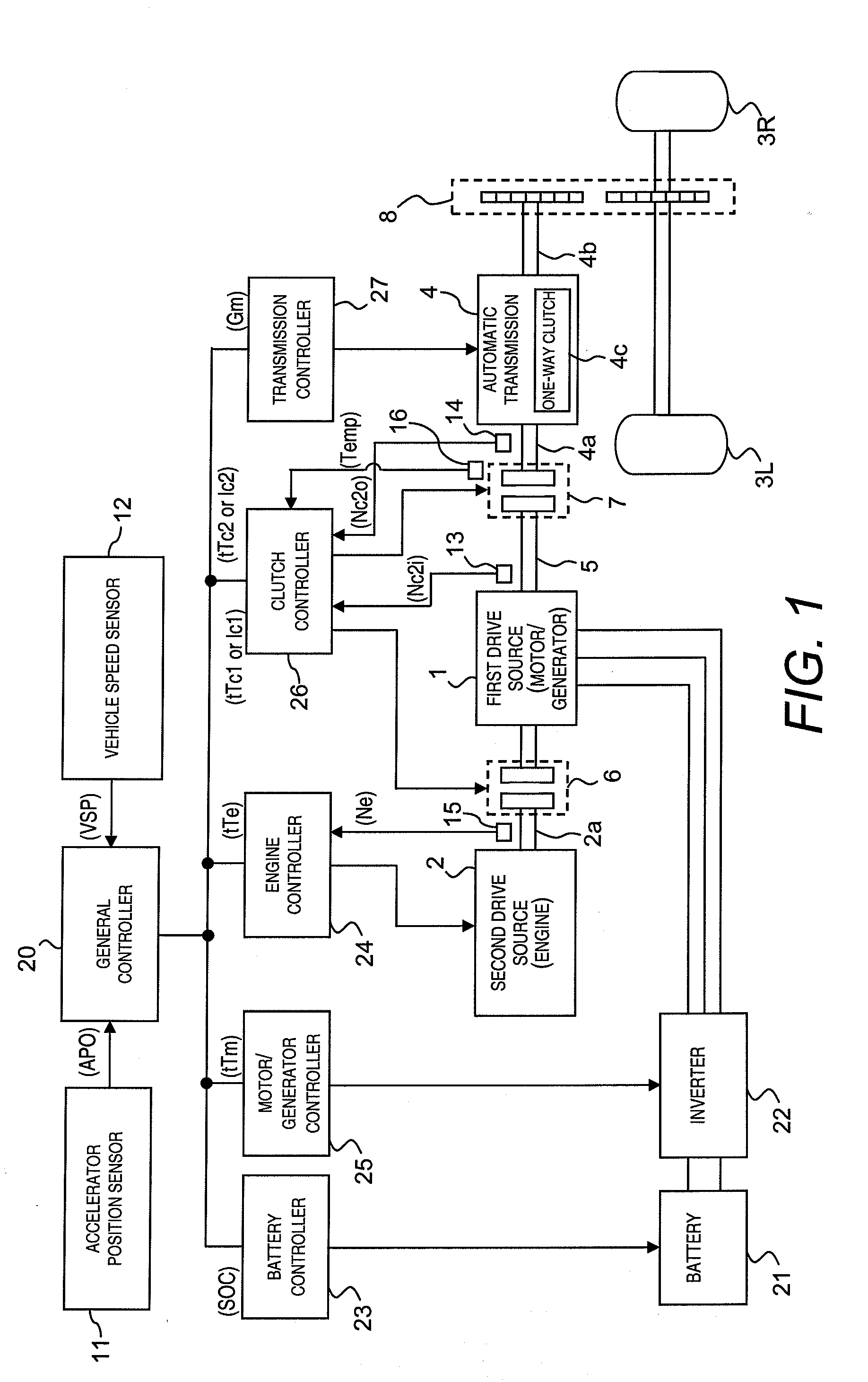
[0029]Referring initially to FIG. 1, a wheel drive train (power train) of a hybrid vehicle having a hybrid vehicle control apparatus in accordance with an illustrated embodiment of the present invention is explained. In this example, the hybrid vehicle is arranged as a rear wheel drive hybrid vehicle. FIG. 1 is an overall schematic block diagram showing a drive train control system of the hybrid vehicle. As shown in FIG. 1, the drive train of the hybrid vehicle in the illustrated embodiment basically includes a motor / generator 1 as a first power source, an engine 2 as a second power source and left...


PUM


Abstract

A hybrid vehicle control apparatus is provided with a motor / generator arranged between an engine and a transmission, a first clutch disposed between the engine and the motor / generator, a second clutch disposed in a power train spanning from the motor / generator to a drive wheel, and a controller. The controller controls the engagement of the first and second clutches to select either an electric drive mode or a hybrid drive mode. The controller executes a rotational speed control of the motor / generator while in a coasting state with torque being transmitted through a one-way clutch of the transmission such that the rotational speed control increases an input rotational speed of the one-way clutch to a value closer to an output rotational speed of the one-way clutch with a difference between the input and output rotational speeds of the one-way clutch becoming equal to a target value.

Description

CROSS-REFERENCE TO RELATED APPLICATIONS[0001]This application claims priority to Japanese Patent Application Nos. 2006-232059, filed on Aug. 29, 2006 and 2007-149568, filed on Jun. 5, 2007. The entire disclosures of Japanese Patent Application Nos. 2006-232059 and 2007-149568 are hereby incorporated herein by reference.BACKGROUND OF THE INVENTION[0002]1. Field of the Invention[0003]The present invention generally relates to a hybrid vehicle control apparatus for selectively controlling power from a motor / generator as well as power from an engine to selectively obtain an electric drive (EV) mode in which the vehicle is driven solely with power from the motor / generator and a hybrid drive (HEV) mode in which the vehicle is driven with power from both the engine and the motor / generator.[0004]2. Background Information[0005]Various hybrid drive apparatus configurations have been proposed for use in hybrid vehicles. One known example of such a configuration is disclosed in Japanese Laid-Op...

Claims


Application Information

Patent Timeline
Patent Type & Authority Applications(United States)
IPC IPC(8): B60W10/08B60K6/48B60K6/547B60W10/02B60W20/00F16H59/46F16H59/74F16H61/04F16H61/68F16H61/684F16H61/688F16H63/50
CPCB60K6/36Y10T477/26B60K6/48B60K6/547B60L2240/421B60L2240/423B60W10/02B60W10/06B60W10/08B60W10/115B60W20/00B60W2510/0638B60W2710/081B60W2710/083B60W2710/085Y02T10/6221Y02T10/6286Y02T10/642B60K6/383Y02T10/62Y02T10/64Y02T10/60B60W20/40
Inventor ASHIZAWA, HIROYUKIMOTOSUGI, JUNADACHI, KAZUTAKA
Owner NISSAN MOTOR CO LTD
Why Eureka
Try Eureka