Prosthetic device and system and method for implanting prosthetic device

a prosthetic device and prosthetic technology, applied in the field of orthopaedic joint replacement, can solve the problems of inconvenient operation, and inability to achieve fit, and conventional tka systems lack the flexibility to enable surgeons

Inactive Publication Date: 2008-03-06
MAKO SURGICAL CORP +1
View PDF37 Cites 601 Cited by
  • Summary
  • Abstract
  • Description
  • Claims
  • Application Information

AI Technical Summary

Problems solved by technology

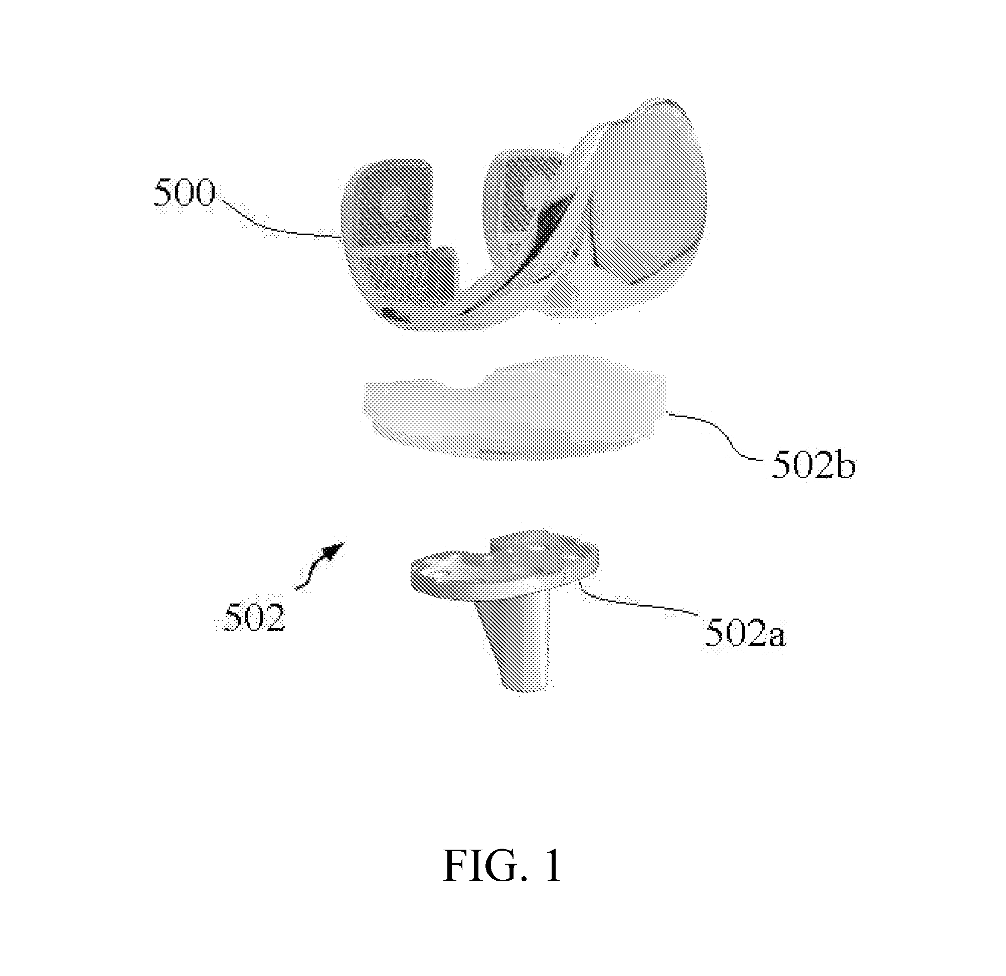
One disadvantage of conventional TKA systems is that the incision must be large enough to accept implantation of the femoral component 500 and the tibial component 502.
Another disadvantage is that the femoral component 500 and the tibial component 502 have standard, fixed geometries and are available in a limited range of sizes.
As a result, the surgeon may be unable to achieve a fit that addresses each patient's unique anatomy, ligament stability, and kinematics.
Additionally, because conventional implant geometry is fixed, the surgeon may be forced to remove healthy as well as diseased bone to accommodate the implant.
Thus, conventional TKA systems lack the flexibility to enable the surgeon to select implant components that are customized to accommodate a patient's unique anatomy and / or disease state.
One disadvantage of such systems is that the modular components, although inserted separately, are connected together inside the patient's body.
Thus, the modular components mimic a conventional TKA system, and, as a result, have limitations similar to those of a conventional TKA system.
As a result, the degrees of freedom, interchangeability, and design variability of each modular component are restricted and the final geometry of the assembled component is fixed.
Thus, conventional modular implants do not enable the surgeon to vary the placement or geometry of each modular component to best suit each patient's unique anatomy, ligament stability, kinematics, and disease state.
Additionally, these systems are designed as non-constraining implants and thus are limited for use in patients with intact ligaments.
As a result, such systems are unable to accommodate patients with disease that has progressed to the central (e.g., anterior) compartment of the femur or who have deficient ligaments.
For example, when a patient has a deficient posterior cruciate ligament (PCL), the PCL may not be able to provide the necessary constraint to the joint.
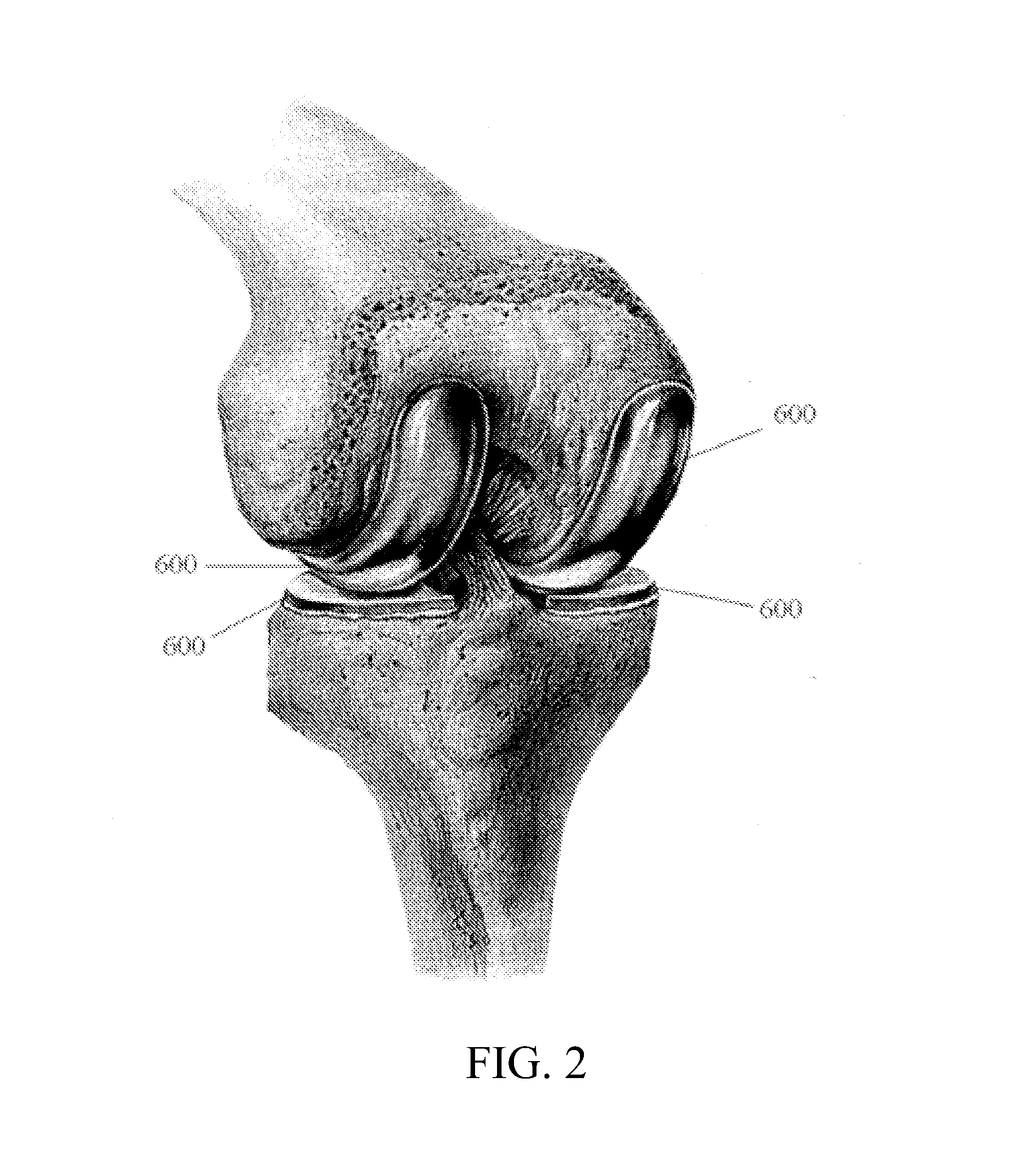
Because conventional unconnected UKA systems only include components for the medial and lateral compartments of the knee, such implants are not suitable for requiring posterior stabilization or resurfacing of the central compartment of the knee.
Another disadvantage of such conventional systems is that the unconnected components 600 require accurate alignment relative to one another.
Conventional freehand sculpting techniques, however, require a high degree of surgical skill and training and may not enable sufficient accuracy in a repeatable, predictable manner.

Method used


Image

  • Prosthetic device and system and method for implanting prosthetic device
  • Prosthetic device and system and method for implanting prosthetic device
  • Prosthetic device and system and method for implanting prosthetic device

Examples


Embodiment Construction

[0047] Presently preferred embodiments of the invention are illustrated in the drawings. An effort has been made to use the same or like reference numbers throughout the drawings to refer to the same or like parts.

[0048]FIG. 4 is a diagram of a knee joint that includes a distal end of a femur 230, a proximal end of a tibia 240, a fibula 260, and a patella 250. The patella 250 moves relative to the femur 230 and the tibia 240 when the knee joint articulates. The femur 230 is joined to the tibia 240 by a medial collateral ligament (MCL) 272, a posterior cruciate ligament (PCL) 278, and an anterior cruciate ligament (ACL) 276. The femur 230 is joined to the fibula 260 by a lateral collateral ligament (LCL) 274.

[0049] The distal end of the femur 230 is conceptually divided into a lateral (i.e., outside) condyle region A, a central (or patellofemoral) region C (which contains a patellar groove 232 having an inverted U-shape), and a medial condyle (i.e., inside) region E. Similarly, the...


PUM


Abstract

A method of implanting a prosthetic device configured to form at least a portion of a joint is provided. The method includes selecting a first component of the prosthetic device configured to be implanted in a body, determining a placement at which the first component will be fixed relative to a bone of the body, selecting a second component of the prosthetic device configured to be implanted in the body, and determining a placement at which the second component will be fixed relative to the bone. The determination of the placement of the second component is not constrained by a connection to the first component.

Description

BACKGROUND OF THE INVENTION [0001] 1. Field of the Invention [0002] The invention relates to orthopedic joint replacement and, more particularly, to a prosthetic device for use in orthopedic joint replacement for resurfacing an articular surface of a bone and a system and method for implanting the same. [0003] 2. Description of Related Art [0004] As shown in FIG. 1, conventional total knee arthroplasty (TKA) systems typically include a femoral component 500 that is implanted on the distal end of the femur and replaces the bearing surfaces of the femur, a tibial component 502 that is implanted on the proximal end of the tibia and replaces the bearing surfaces of the tibia and meniscus, and a patellar component (not shown) that replaces the articular surface of the patella. The femoral component 500 is typically a single solid component. The tibial component 502 may include a tibial baseplate (or tray) 502a that is affixed to the bone and a tibial insert 502b that is disposed on the t...

Claims


Application Information

Patent Timeline
Patent Type & Authority Applications(United States)
IPC IPC(8): A61F2/38
CPCA61F2/38A61F2002/4632A61F2002/3895A61F2002/30604
Inventor HAJAJ, BINYAMINOTTO, JASON K.ABOVITZ, RONYBROWN, STEVEN B.BANKS, SCOTTFREGLY, BENJAMIN J.MEARS, DANA C.
Owner MAKO SURGICAL CORP
Why Eureka
Try Eureka